Fuel Cells
Fuel cells produce electrical power from hydrogen and oxygen with by-products of water and heat. Among other uses, fuel cells can be used for transportation and energy storage applications.
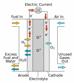
Fuel cells convert chemical energy into electrical energy. During electrochemical reactions, there are two electrochemical half reactions that occur—reduction and oxidation. During reduction reactions, reactants gain electrons, and in oxidation reactions, reactants lose electrons. In fuel cells, these half reactions occur at the anodic and cathodic interfaces which are separated by an electrolyte. For example, in solid oxide fuel cells (SOFCs), oxide ions exist in the solid electrolyte membrane and the cathodic reaction produces them on one side of the electrolyte. It is generally assumed that the concentration of oxide ions does not vary in concentration through the electrolyte membrane, however, the oxide ions are driven across the electrolyte membrane due to the electric field. The anodic reaction on the other side of the electrolyte consumes the oxide ions. By separating the electrochemical half reactions (on either side of the electrolyte), fuel cells can therefore harness the transport of species to generate electrical power.
These electrochemical reactions occur at the interface between fluid and solid phases. There are different types of fuel cells which you can categorize by the type of membrane that is present at the interface between the fluid and solid phases.
Solid Oxide Fuel Cells (SOFC)
SOFCs are used to store energy for high temperature applications (900–1000 ºC).
SOFCs are mostly made of porous ceramic materials which require high temperatures before they become ionically conductive. The solid oxide material that is used for the electrolyte must reach a temperature that is high enough to support the kinetic transport of oxide ions through it from the cathode to the anode.
The electrons () that are produced in this reaction are conducted electrically from the anode, through an external circuit, to the cathode. This flow of electrons generates electrical power. Oxygen () diffuses through the porous cathode and reacts with the electrons to form oxide ions ().
The oxide ions are then transported from the cathode, through the electrolyte, to the anode. The series of reactions continue as long as there is a supply of hydrogen fuel at the anode and oxygen at the cathode.

When designing a fuel cell, one of the most significant challenges is to maximize its efficiency and performance. The aim is to maximize the transport of species and minimize energy losses in the cell, for example, energy loss due to diffusion, or ohmic losses due to ohmic resistance within ceramic components. The transport of species and energy losses are affected by variables such as the thickness, surface area, or material of the porous layers within the cell. The characteristics of the TPB have a significant impact on the electrochemical performance of the cell.
When simulating fuel cells in Simcenter STAR-CCM+, you can define separate solid continua for the anode, cathode, electrolyte membrane, and tabs—where all components except the tabs are reactive domains. You can then use separate fluid continua for the air and fuel domains—or if the air and fuel streams mix at any point, use one continuum. Follow the guidelines in the workflow, Modeling Electrochemical Surface Reactions.
There are some important considerations to account for when modeling SOFCs when using the present implementation of Simcenter STAR-CCM+.
In particular, the setup must obey the first law of thermodynamics—energy cannot be created or destroyed. The difference between the overall energy of the species entering a reactive domain must be equal to the overall energy of the species leaving that domain—after accounting for the sum of the energy that the electrochemical surface reactions create and consume within that domain. You can check the energy conservation in Simcenter STAR-CCM+ by creating reports for electric power flux and energy loss and then using these reports to create monitors and a single plot.
Since the reaction sites are in close proximity to the fuel and air inlets in the reactive domains, there is significant flow boundary diffusion. With flow boundary diffusion, it is possible that specifying the total flux and species concentrations leads to flux of some species in the opposite direction of the mean flow. Therefore, another important consideration is to decide if the simulation ignores flow boundary diffusion in the overall computations.