Setting Up the Replace Part Operation with Local Volume Meshing
Here, you define a replace part operation that uses a file global parameter for the file being read from disk. You also assign some parts to their correct operation in order to assemble a meshing pipeline that Design Manager can execute using only the file global parameter.
In this scenario when the spoiler design is replaced, you must be able to successfully re-execute the subtract operation after the replace part operation is complete.
Before creating the replace part operation, define a file global parameter:- In Simcenter STAR-CCM+, right-click and select .
- Rename the node to PartReplacement.
- In the Properties window, click
 (Custom Editor), and select Spoiler1.x_b.
In order to replace a part within the meshing pipeline, you first create a duplicate part that acts as a placeholder in operations.
- In , right-click the Spoiler node and select Duplicate.
- Rename the duplicate part to ReplacePart.
- Right-click the node and select .
- In the Create Replace Part Operation dialog:
- Set Obtain Mesh From to File.
- Click the parameter selector
 next to File and select PartReplacement. Click OK.
 - For the Target Part, select ReplacePart.
- Click OK.
- Select the Fluid Domain subtract operation and set the Input Parts to:
- Car
- Domain
- ReplacePart
- Select the node and set Part Surfaces to ReplacePart.
- Right-click the node and select Execute All. This step executes all operations including mesh generation.
In cases where there are design changes, you can use local volume meshing to remesh only a specific part without regenerating a complete mesh. To mesh the spoiler using local volume meshing:
- Select the Automated Mesh node and activate the Perform Local Meshing option. The Local Extents node is added to the automated mesh operation.
- Create a volume extent:
- Right-click the node and select Execute All.
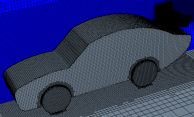
To visualise the mesh:
- Click
 (Make Scene Transparent) to deactivate transparency.
 -
Right-click the Scenes node and select .
To display the latest scenes:
- Right-click on the Scenes node and select
You can now run the simulation.
- In the Solution toolbar, click
 (Run). The Residuals display is automatically opened and shows the progress of the solver.
 - Once the simulation is complete, save the file.