Monitoring the Solution
Create a report, monitor, and plot to track the moment of force on the surface of the rotating blades during the simulation. Monitoring this value helps to make sure that the solution is converging within each time-step.
- Right-click the Reports node and select .
- Select the Moment 1 node, and set Parts to .
To create the monitor and
plot that are based on this report:
-
Right-click the node and select Create Monitor and Plot from
Report.
The Moment 1 Monitor node appears under Monitors and the Moment 1 Monitor Plot node appears under Plots.
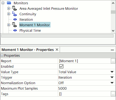
-
Select the node and set Trigger to
Iteration.
Monitoring the moment during time-steps provides the data for intra time-step convergence checks.
Normally, it is important
to monitor convergence between time-steps. However, for most plots in unsteady cases
it is more useful to examine the solution progress by reporting a quantity on every
time-step rather than for every iteration. Modify the Area Averaged Inlet
Pressure Monitor plot and the vector scene to update every
time-step.
- Select the node and set Trigger to Time Step.
- Select the node and set Trigger to Time Step.
Make sure that the X-Axis Monitor is set to the correct type for each
plot:
- Select the node and set X-Axis Monitor to Physical Time.
- Select the and set X-Axis Monitor to Iteration.
- Select the node and set Shape to Filled Circle.
- Save the simulation.