Turbomachinery Mesher: Compressor Stage
When modelling the flow in turbomachinery applications, a flow-aligned structured mesh is required for accurate solution analysis. The Turbomachinery Mesh operation in Simcenter STAR-CCM+ generates a flow-aligned structured mesh from user-specified input surfaces and parameters.
In this tutorial, you
generate the mesh for a single compressor stage in a gas turbine
engine.
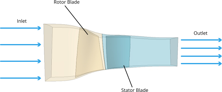
The simulation includes two regions—one for the rotor passage and one for the stator passage of a gas turbine engine. Each region is enclosed by a periodic interface and contains a single blade. The surface between the rotor and stator passages forms a mixing-plane interface to transfer circumferentially averaged flow field data between the two rotationally periodic regions.
The simulation includes two regions—one for the rotor passage and one for the stator passage of a gas turbine engine. Each region is enclosed by a periodic interface and contains a single blade. The surface between the rotor and stator passages forms a mixing-plane interface to transfer circumferentially averaged flow field data between the two rotationally periodic regions.
The rotor passage geometry contains a tip gap between the rotor blade and the shroud surface. However, there is no tip gap between the stator blade and hub.
This tutorial focuses on the meshing workflow for turbomachinery applications. Hence, no physics set up is required for this case.