Setting Up a Line Surface for Plotting
For comparison with the experimental data, a part needs to be created on which to plot the duct wall pressure ratio.
Create the part by intersecting a plane with the surface corresponding to the duct wall, resulting in a line surface.

- Right-click the node and select .
-
In the intake window, right-click the node and select .
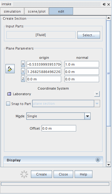
An interactive in-place dialog appears with default settings to allow definition of the derived part.

- Click Input Parts to activate the Select Objects dialog.
-
Expand the
nodes and select
Port Wall only.
Note The Fluid region must be deselected. - Click OK.
- In the Plane Parameters box, enter values for the y-coordinate: 0.001 for the origin and 1 for the normal. Set all other values to zero.
- In the Display box, select No Displayer.
-
Click
Create.
In the intake window, a node representing the implicit surface created is added under the node: .

-
Click
Close in the dialog.
It is now possible to plot data on the new implicit surface.
- Save the simulation.