Manipulating Regions and Boundaries
Combine the separate mesh blocks into a single contiguous mesh, then rename the mesh entities before continuing with the simulation.
Use the following steps:
-
In the
intake window, open the
node.
See three separate regions, corresponding to the three mesh blocks that were imported.
-
Click to select each of the region nodes (Fluid_1,
Fluid_1 2, and
Fluid_1 3) in turn.
The selected region is highlighted and labeled in the Geometry Scene 1 display.

- Create internal interfaces.
- Fuse the regions and boundaries.
Using internal interfaces is advantageous if the mesh is to be manipulated further at a later stage, since interfaces can easily be deleted and created. However, there is likely to be some (most likely small) computational overhead that is associated with the interface. In this case, since the mesh does not need to be changed, combine the regions and fuse the adjacent boundaries, creating a single contiguous mesh. The process of “fusing” creates a (possibly non-conformal) interface, and then merges that interface into the mesh.
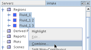
To combine the separate regions into one, use Shift Click to select all three region nodes.
-
Right-click and select
Combine... .
-
In the
Combine Regions dialog, make sure that all regions under it are selected.
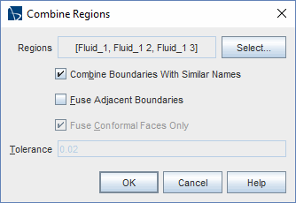
- Activate Combine boundaries with similar names.
-
Click
OK to combine the regions without fusing the boundaries.
As a result of this operation, a single region node remains.

- Rename the node to Fluid.
Now that the regions have been combined, fuse the adjacent boundaries that are currently separating the regions. The mesh is not conformal at these boundaries, so a non-conformal intersection needs to be computed as part of the fusing process. Essentially, an interface is created and then merged into the mesh.
The intersection process requires the specification of a tolerance. Use a value of 0.02 (default 0.05) and then perform checks to make sure that this is suitable.
Before creating interfaces, the freestream boundary types must be redefined as walls. This allows the solution to be initialized without activating a flow model, normally a requirement of freestream boundaries.
- Open the node.
-
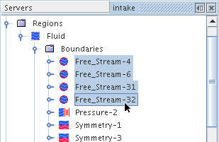
Select all the freestream boundary nodes:
,
,
and
and set the
Type to
.
-
Select the
node, then use the
Ctrl Click approach to select the
node.
(It is important to select the boundaries in this order.)
- Right-click and select .
- Select the node and set Geometric Tolerance to 0.02.
-
Click
 (Initialize Solution) on the toolbar or select
.
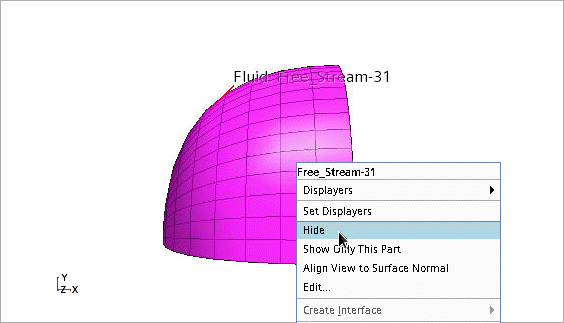
- To gain access to them, first locate the part by clicking its node.
-
Right-click that part in the scene and select
.
-
Next, select the nodes of the two internal interface boundaries, then click the
 (Reset View) button on the toolbar to bring them into focus. (Zoom and rotate if necessary.)
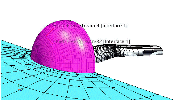
-
Right-click the
node and select
.
- Click Yes in the confirmation dialog.
-
Select the nodes of the
and
boundaries (in that order), right-click and select
.
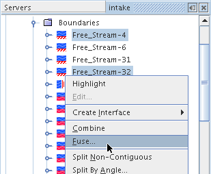
The sequence of boundary selection can affect the results of the fuse operation. When you fuse boundaries, Simcenter STAR-CCM+ attempts to take the second boundary selected by you and project it onto the first.
-
In the
Fuse Boundaries dialog, make sure that these boundaries are selected:
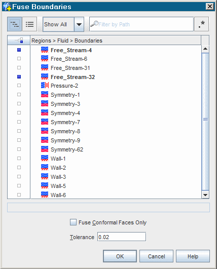
-
Click
OK.
Both these boundaries disappear from the tree, since fusing boundaries incorporates them into the interior mesh grid.
- Repeat the fusing process for the and boundaries. Again, use the default tolerance, 0.02.
-
Combine (do not fuse) the
and
boundaries by selecting their nodes, right-clicking, and selecting
.
This creates a single freestream boundary entity.
- Select all the remaining symmetry plane nodes, right-click, and select .
- Select the node and look in the Geometry scene.
-
To see the part more clearly, click
 (Make Scene Transparent).
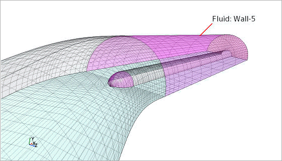
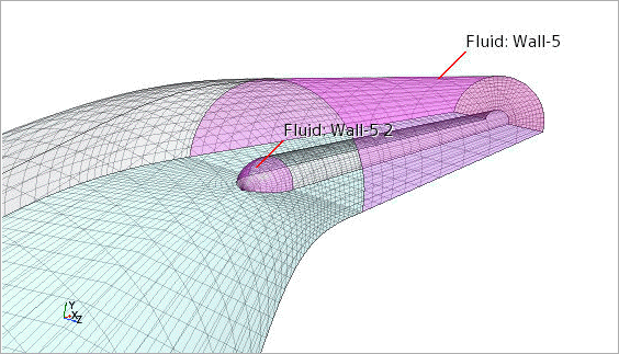
This boundary includes two non-contiguous surfaces.
-
To correct this, right-click the
node and select
.
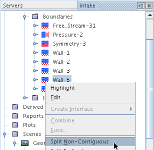
-
Select the
node and then the new
node separately. The split action has made them into two separate boundaries.
-
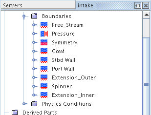
Rename the following nodes:
Node New Name Free_Stream-31 Free_Stream Pressure-2 Pressure Symmetry-3 Symmetry Wall-1 Cowl Wall-2 Stbd Wall Wall-3 Port Wall Wall-5 Extension_Outer Wall-5 2 Spinner Wall-6 Extension_Inner This portion of the simulation tree appears as shown below:
- Save the simulation.