Basic Method
In this section, “local” refers to the value stored in each cell. The goal in the dual stream heat exchanger is to specify or compute a local/cell heat transfer coefficient (multiplied by the local heat exchanger area) as a function of the local velocity of the cold stream.
The local heat exchange between the hot and the cold stream, , is given by:
where the “+” is for the cold stream and “-” is for the hot stream (that is, hot stream loses heat to the cold stream). and refer to the local temperatures of the hot and cold streams respectively. This heat exchange is then added as a source term to the corresponding fluid energy equation after scaling by the cell volume, that is:
where is the cell source term, is the cell volume, is the number of cells in the heat exchanger, and is the volume of all the cells in the heat exchanger.
UAL Polynomial Option
In the UAL Polynomial option, the specified polynomial function is used to compute as a function of the local velocity of the cold stream. In the UAL Table option, is interpolated from the specified table of cold flow velocity vs. .
UAG Table Option
In the UAG Table option, refers to the overall heat transfer coefficient (multiplied by the heat exchanger area) across the entire heat exchanger, such that,
where is the overall heat transfer across the entire heat exchanger, and and refers to the inlet temperatures of the hot and cold streams respectively. The UAG Table is specified as a table of cold flow mass flow rate vs. , which may be obtained from test/experimental data. You also specify other data pertaining to the test conditions including:
- Hot stream mass flow rate .
- Inlet temperatures of the cold and hot streams.
- Specific heats of the cold and hot streams.
- Density of the cold fluid .
Using these input data, the specified UAG table is internally converted into a UAL table (as in the UAL Table option). This conversion is performed by considering a heat balance between the cold and hot streams as detailed in the following algorithm.
Repeat the following steps for each entry in the UAG Table:
- Retrieve cold stream mass flow rate and from the UAG Table.
- Compute the target overall heat transfer rate:
- Guess = / Nc, where Nc is the total number of cells in the heat exchanger.
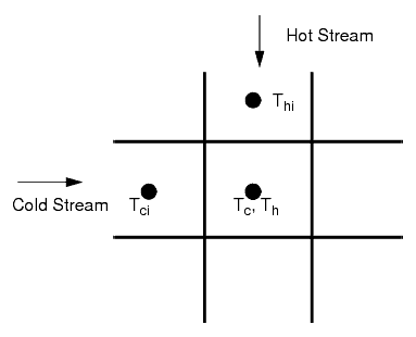
- Build a linear system of equations, by constructing the following set of equations in each cell:(228)
where , , and are local cell unknown temperatures as shown in the following figure.

Assemble the system for all the cells in the heat exchanger, and solve for the unknown cell temperatures and . Boundary conditions are required only at the inlet boundaries, at which the cell temperatures are set to the user-specified and for the cold and hot streams respectively.
- Compute the mean temperature difference between the cold and hot streams:(229)
- Compute the estimated overall heat transfer .
- Update .
- Repeat steps 4 to 7 until the user-specified Maximum Solver Iterations have reached or the convergence criteria is met, where is the user-specified convergence tolerance.
- Store the converged and cold flow velocity where is the heat exchanger cold stream inlet boundary area into the internal UAL table.
The above algorithm is invoked once before the first energy solver iteration, and the internally stored UAL table is reused in the subsequent iterations for computing the energy source term as in Eqn. (226). Whenever any UAG Table input is changed, the internal UAL table is recomputed. in Eqn. (226) is then interpolated based on the local cold stream velocity from this internal UAL table.
The maximum allowable heat transfer rate in a heat exchanger occurs when the temperatures of each stream do not change at all from inlet to outlet (maximum temperature difference). Then the heat transfers to or from each stream are:
and
These heat transfers would have to be equal, and therefore the maximum heat transfer is limited to the minimum of these two values: the one for which is a minimum. Usually, this minimum value is for the hot fluid since coolants have high specific heats.
The target heat transfer rate must be chosen such that it is always smaller than the minimum of Eqn. (230) and Eqn. (231), that is:
Q Table Option
The Q Table option is identical in functionality to the UAG Table option, except that you specify the overall heat transfer instead of in the input table. is then computed using Eqn. (227).
Q Map Option
To compute the local UAL, a linear system of algebraic equations is solved iteratively by considering the heat balance between the cold and the hot streams, preserving the target heat exchange rate, for each row of the Q Map (that is, for each value of the cold stream and hot stream mass flow rates). This UAL table is computed internally only once initially (or whenever any input for the Q Map is changed). The UAL table is then used to determine the coefficients in the following curve using least squares regression.
In Eqn. (233), , and are the coefficients that are determined by fitting the UAL table data to the above curve using least squares regression, and are the cold flow and hot flow local velocities, and and are the cold flow and hot flow exponents (which by default are taken to be 0.8). After the coefficients are determined, Eqn. (233) is used to determine the local UAL for a given cold flow and hot flow local cell velocities in the energy equation.