Coupling Simcenter STAR-CCM+ to GT-SUITE
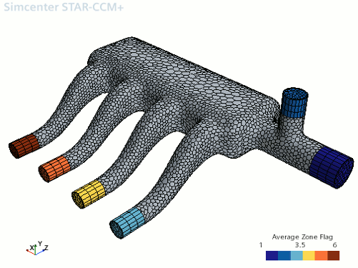
Instruct Simcenter STAR-CCM+ to launch GT-SUITE in server mode and connect to it. Use the average zone flag field function to visualize the areas where the flow is approximately one dimensional.
-
Expand the node and set the following properties:
Node Property Setting GT-SUITE Version Version v2022 Launch Partner Option Option Launch Application (default) - Expand the node.
-
Select the GT-SUITE Model File node and set GT-SUITE Input File to
GT-SUITE_caseFiles/CFDCoupling_Setup.gtm. If you saved
the input file to a different location, adjust the file path as required.
You can type the file path and name manually, or you can click
 (Custom
Editor) and use the dialog to navigate to the file.
In order to launch
GT-SUITE in server mode,
Simcenter STAR-CCM+ requires you to specify the location of the
GT-SUITE installation and license file using two environment variables,
$GTIHOME and
$GTISOFT_LICENSE_FILE, respectively.
- If you did not define the required global variables on your system, specify them locally by setting the following properties:
Node Property Setting GTIHOME Environment Variable GTIHOME [Path to GT-SUITE Installation] GTISOFT_LICENSE_FILE Environment Variable GTISOFT_LICENSE_FILE [Path to GT-SUITE License]
-
Right-click the
Link 1 node and select
Launch and Connect.
The GT-SUITE solver is started in the background, waiting for Simcenter STAR-CCM+ to begin running its solver. Clearing the solution stops the GT-SUITE solver and breaks the connection to Simcenter STAR-CCM+. If you clear the solution, restart the GT-SUITE solver as outlined above.
Visualize the volume where physics values and mass fractions are averaged and sent to
GT-SUITE. Inspect the zone and determine whether the flow is relatively one dimensional.
- Create a scalar scene.
-
Edit the Scalar Scene 1 node and set the following
properties:
Node Property Setting Outline 1 Surface Activated Mesh Activated Scalar 1  Parts
Parts
Parts Cyl1 Cyl2 Cyl3 Cyl4 EGR Intake Wall  Scalar Field
Function Average Zone Flag Min 1 Max 6  Color Bar
Levels 6 -
Click
 (Save-Restore-Select views) and restore
View 1.
-
Initialize the Solution.
A scene similar to the one shown below appears.

The scalar values, which relate to which boundary was created first in Simcenter STAR-CCM+, are of no significance and simply highlight the individual zones.
- Save the simulation.