Deicing
Deicing is assumed to be a quasi-steady process.
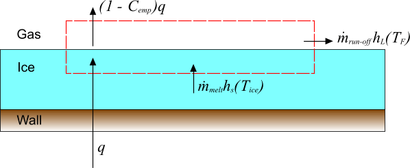
An ice layer at temperature is melted with a wall heat flux , of which a proportion is absorbed in the ice layer. Melted ice at the freezing temperature escapes as run-off which cannot refreeze in the current model. The mass and energy fluxes that are associated with this process are illustrated in the diagram below:

The mass balance for the deicing process is simply
As it is assumed that run-off cannot refreeze, there is the additional constraint that and hence from Eqn. (214), .
The energy balance for this process, neglecting the kinetic energy that is associated with the mass fluxes, is:
where is the enthalpy of the solid ice at the temperature of the ice layer, and is the enthalpy that is associated with the melting ice at the freezing temperature. These enthalpies are related to temperature by:
Using these relations with the mass balance, and rearranging, gives an explicit expression for the melting rate:
The constraint, , must be imposed on this equation. If Eqn. (218) predicts a negative , it is clipped to zero.
Given , the ice thickness, s, can be updated using:
where is the density of the ice layer.
Accretion
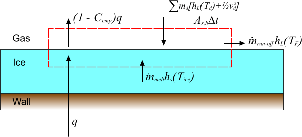
The preceding analysis is extended to include an additional incident mass flux of liquid droplets, each with mass , temperature and velocity . This expression is intended to represent liquid droplets impinging on the surface. The various contributions to the overall energy balance are depicted below:

In the above diagram, is the surface area of the boundary face onto which the droplets impinge and is the time-step. The term:
indicates the overall energy flux due to the impinging droplets.
The mass balance is therefore given as:
where:
In addition to the constraint that , there is also . The constraint on is now , that is, freezing is allowed but no faster than the incoming liquid rate.
The energy balance for this process is:
giving:
A similar analysis can be made for the accretion of solid particles.
Accretion Ratio
Following Makkonen [195], it is useful to define the accretion ratio for non-zero as:
This quantity characterizes the nature of the accretion process. When there is no run-off and the accretion is “dry”, which tends to form rime ice. Otherwise there is some run-off, and the “wet” growth tends to form glaze ice. The accretion ratio is sometimes also known as the “freezing fraction”.