Solid Oxide Fuel Cell
Solid Oxide Fuel Cells (SOFCs) harness the chemical energy that is released by electrochemical reactions and convert it to electrical energy. SOFCs typically consume hydrogen and oxygen and only produce water as a waste product.
SOFCs are electrochemical cells (or stacks of cells) which are composed of electrodes (an anode and a cathode), a solid oxide electrolyte, and current collectors.
This tutorial demonstrates the workflow for setting up and simulating a single planar button solid oxide fuel cell. The mole fraction of oxygen is visualized in relation to the reaction flux. It is important to check that the transport of oxygen through the cathode is sufficient enough to avoid oxygen starvation—which would limit the reaction rate and damage the fuel cell components. Setting up a case in this way with a single cell is useful to first determine the optimal set-up, transport mechanism, and reaction mechanism before scaling-up to simulate multiple cells in a stack.
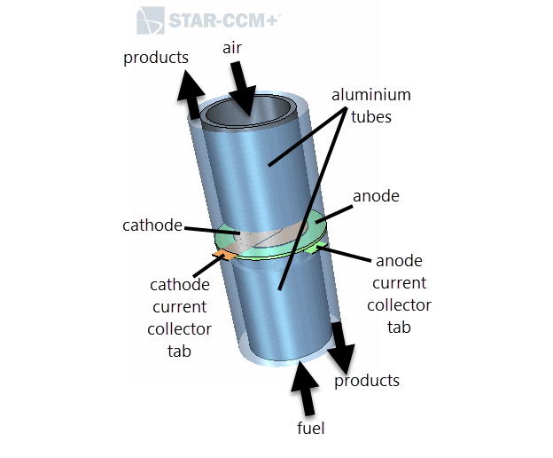
The following diagram shows the different components of the planar button SOFC.

The planar button SOFC is placed inside a cylindrical casing. The complete geometry consists of an external casing which is intersected by the solid oxide electrolyte membrane and the anode and cathode current collectors. Within the volume of the external casing, there are internal aluminium tubes. Products of the reactions leave the SOFC from the space between the external casing and the tubes.
| Components | Key Features |
|---|---|
| Solid Oxide Electrolyte Membrane |
|
| Anode and Cathode | Fluid Regions with porous phases |
| Anode and Cathode Current Collectors | Solid Regions which can conduct an electric current |
| Air and Fuel |
|
| Tubes | Solid Regions |
A gas phase fuel mixture (97% hydrogen and 3% water vapour) enters through the centre of the inner aluminum tube that is coincident with the anodic side of the button cell. A gas phase air mixture (21% oxygen and 79% nitrogen) enters through the centre of the inner aluminum tube that is coincident with the cathodic side of the button cell. The hydrogen in the fuel stream diffuses through the porous anode and reacts at the interface to the solid oxide electrolyte membrane. This interface represents the catalyst layers which include the triple phase boundaries, and will therefore be referred to as the TPB.

In Simcenter STAR-CCM+, the direction of the electrochemical reaction current is positive in the direction of the solid to the fluid. In many electrochemical set-ups, this direction of reaction current is suitable as the solid is the electrode and the fluid is the electrolyte. However, in SOFCs, the solid oxide membrane is the electrolyte and the fluid is within the porous electrode. The Solid Ion model in Simcenter STAR-CCM+ is in reduction current convention, leading to negative SOFC anode current density (electrons move from the anode to the cathode). Therefore, the anodic reaction—which is an oxidation reaction:
is given in the reduction form:
Prior to participating in the reaction at the anode, the oxide ions are transported across the solid oxide membrane. These oxide ions are created by the reaction that occurs at the surface between the cathode and the solid oxide electrolyte membrane: