Coordinate Cell Clustering
Simcenter STAR-CCM+ allows you to group mesh cells into clusters, based on their position with respect to a specified coordinate system, and provides a field index for querying values based on cluster. You can create threshold reports based on these clusters of cells.
-
In the relevant physics continuum, activate the Coordinate Cell
Clustering model.
For information on other model requirements, see Coordinate Cell Clustering Model Reference.
To define how the mesh is divided into clusters, there are two
options:
-
Choose from:
- Right click , and select .
This allows you to specify the number of subdivisions across each axis. The subdivision points are distributed equidistantly along each axis.Or- Right click , and select .
This allows you to specify a non-equidistant clustering distribution along each axis. A linear parameter is used to specify the clustering with the control points being fitted to the bounding box of the domain to be clustered -
Select the node and set the Cluster Merging
Threshold in the
Properties window.
For more information see Coordinate Cell Clustering Solver.
-
Select the node and set the following properties:
Property Setting Coordinate System Select the coordinate system with respect to which the mesh is divided into clusters. You can select a coordinate system of any type. Subdivisions (for Subdivision option only) Specify the number of divisions along each axis of the specified coordinate system. Use the format [#1, #2, #3], where #i denotes the number of divisions for axis i. Control Point on First Axis (for Control Point option only) Specify the parameter control points along the first axis of the coordinate system, including start and end points, as a vector. The input will be normalized to the bounding box of the domain and needs to contain at least two values. Control Point on Second Axis (for Control Point option only) Specify the parameter control points along the second axis of the coordinate system, including start and end points, as a vector. The input will be normalized to the bounding box of the domain and needs to contain at least two values. Control Point on Third Axis (for Control Point option only) Specify the parameter control points along the third axis of the coordinate system, including start and end points, as a vector. The input will be normalized to the bounding box of the domain and needs to contain at least two values.
To divide the mesh into clusters:
- Run the Coordinate Cell Clustering Solver for at least one iteration. For example, you can step the simulation or run it.
To visualize the clusters:
-
Create a scalar scene for the region of interest. For the
scalar displayer, set Scalar Field to
the Cell Cluster Index function.
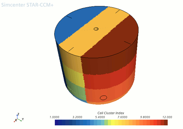
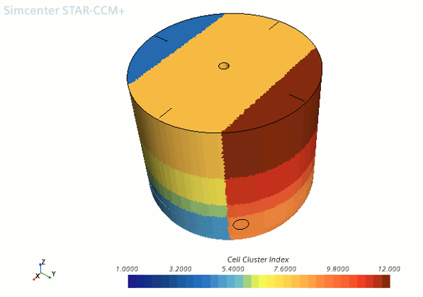
The following images show cell clustering with respect to the Laboratory coordinate system. On the left-hand side it shows the clustering formed using the Subdivisions option with a Subdivision setting of [1,3,4]. On the right-hand side it shows the clustering formed using the Control Points option with a Control Points setting of [0,1], [0,0.2,0.8,1], and [0,0.4,0.5,0.7,1] is the first, second, and third axis respectively.


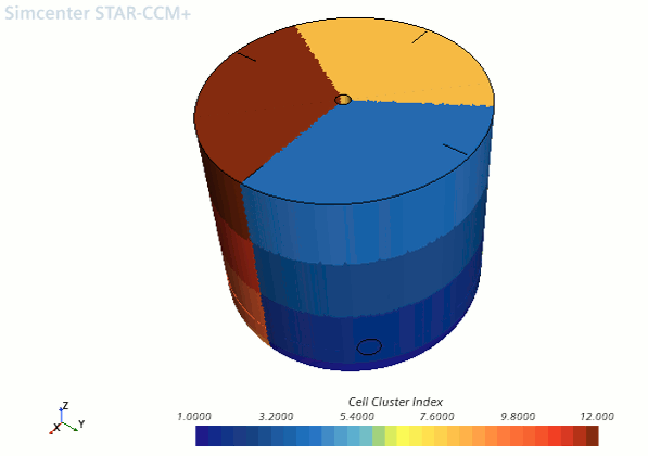
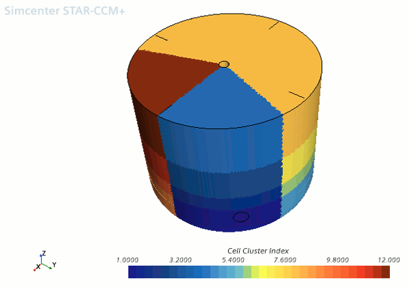
These two types of clustering are present in any coordinate system as shown by the following image which represent the same clustering set-ups as the previous examples but using the Cylindrical coordinate system.

You can use cell clusters in reports. For example, for large
meshes, you can report field data for one or more clusters, rather
then the entire domain. To use clusters in reports:
-
Create either a threshold derived part or cell-set using the
Cell Cluster Index field
function as scalar field for the threshold.
For more information, see Defining a Threshold and Creating a New Cell Set Using a Threshold.
- Create the required report, using the threshold part as input part.