GT-SUITE Co-Simulation
Simcenter STAR-CCM+ allows for two-way co-simulation with GT-SUITE, a multiphysics simulation tool from Gamma Technologies. GT-SUITE provides a modeling framework for the design and analysis of engineering systems, such as engines, vehicles, and thermal-hydraulic networks.
During the co-simulation, GT-SUITE drives the overall one-dimensional system simulation, while Simcenter STAR-CCM+ models the flow within components that require a three-dimensional analysis. For example, you can use Simcenter STAR-CCM+ to model an intake manifold that forms part of an engine analysis designed in GT-SUITE.
Co-Simulation Interface
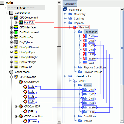
- CFD Component—represents the component that is modeled in 3D using Simcenter STAR-CCM+.
- CFD Interfaces—mark the 1D/3D interfaces between GT-SUITE and Simcenter STAR-CCM+.
- CFD Connections—define the physical conditions and values at the 1D/3D interfaces.

Co-simulation zones and CFD connections must match in number and name.
Exchanged Fields
Co-simulation supports coupling between CFD connections (either CFDFlowConn or CFDFlowConnBeta connections) and Simcenter STAR-CCM+ boundaries of type Mass Flow Inlet, Velocity Inlet, or Pressure Outlet.
- the Simcenter STAR-CCM+ boundary type
- the GT-SUITE CFD Interface Condition that you define for the CFD connection
| Simcenter STAR-CCM+ Boundary Type | GT-SUITE CFD Connection | GT-SUITE CFD Interface Condition Imposed by GT | Imported from GT-SUITE | Exported to GT-SUITE |
|---|---|---|---|---|
| Velocity Inlet | CFDFlowConn | Flow (velocity or mass flow rate) |
|
|
| CFDFlowConnBeta | Flow (CFD imposes GT pressure): Velocity | |||
| Mass Flow Inlet | CFDFlowConn | Flow (velocity or mass flow rate) |
|
|
| CFDFlowConnBeta | Flow (CFD imposes GT pressure): Velocity | |||
| Flow (CFD imposes GT pressure): Mass Flow Rate |
|
|||
| Pressure Outlet | CFDFlowConn | Pressure | Depending on the flow direction, either:
|
|
| CFDFlowConnBeta | Pressure (CFD imposes GT velocity) | |||
| Pressure (CFD imposes GT mass flow) |
|
At a Mass Flow Inlet boundary, Simcenter STAR-CCM+ applies the mass flow rate that is calculated from the imported fields (either velocity and density, or mass).
| Flow Direction | Imported from GT-SUITE | Exported to GT-SUITE |
|---|---|---|
| Entering the Simcenter STAR-CCM+ boundary |
|
-- |
| Leaving the Simcenter STAR-CCM+ boundary | -- |
|
At a Mass Flow Inlet boundary, Simcenter STAR-CCM+ applies the total temperature that is calculated from the imported static temperature and velocity. At a Velocity Inlet boundary, Simcenter STAR-CCM+ directly applies the static temperature imported from GT-SUITE.
GT-SUITE and Simcenter STAR-CCM+ do not exchange turbulence values. Turbulence values are specified in Simcenter STAR-CCM+ at the boundary level, in the usual manner.
Before sending data back to GT-SUITE, Simcenter STAR-CCM+ averages the computed fields across sampling volumes adjacent to the coupled boundaries, to convert the three-dimensional fields to one-dimensional values. Volume averaging is important when significant three-dimensional effects occur near the coupled boundary. The co-simulation provides optimum results when the flow in the sampling volumes is approximately one-dimensional.
GT-SUITE co-simulation uses an explicit coupling scheme, that is, data exchange occurs once per time-step.
Multi-Component Gases: Coupled Material Components
- prod_ar: Argon
- prod_co: Carbon Monoxide
- prod_co2: Carbon Dioxide
- prod_h: Monatomic Hydrogen
- prod_h2: Hydrogen
- prod_h2o: Water
- prod_n: Monatomic Nitrogen
- prod_n2: Nitrogen
- prod_no: Nitric Oxide
- prod_o: Monatomic Oxygen
- prod_o2: Oxygen
- prod_oh: Hydroxide
- prod_so2: Sulphur Dioxide
You associate the GT-SUITE species with corresponding mixture components or passive scalars in Simcenter STAR-CCM+. Mixture components represent GT-SUITE species that influence the bulk flow, that is, species that have non-trace quantities. Passive scalars represent GT-SUITE species that do not influence the bulk flow, that is, species that have trace quantities.
The species mass fractions are exchanged at the co-simulation interface, as described in the previous section.
GT-SUITE Coupling Libraries
| Platform | Library File Location |
|---|---|
| Linux | [GTIHOME]/[GT-SUITE_version]/GTsuite/bin/linux_x86_64/coupling/libgtlink_dp.so |
| Windows | [GTIHOME]/[GT-SUITE_version]/GTsuite/bin/win64/coupling/gtlink_dp.dll |
where [GTIHOME] is the path to the GT-SUITE installation and [GT-SUITE_version] is the version of GT-SUITE.