Displaying Remainder Boundaries
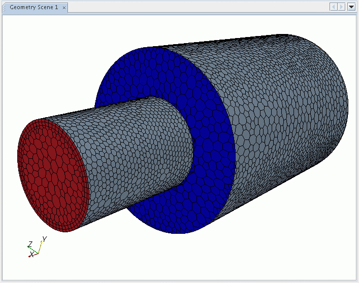
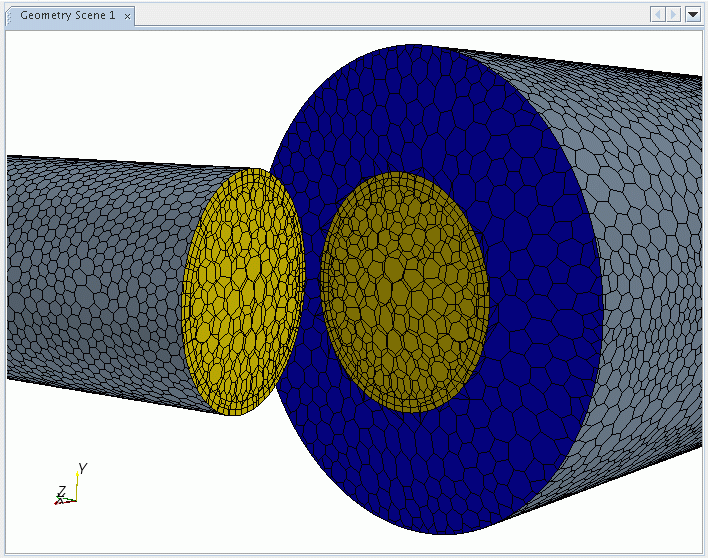
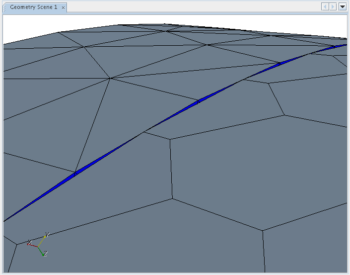
If the original boundaries from which the interface is created do not completely match, the intersection process leaves some boundary faces in the original boundaries. These are called remainder boundaries.
There are two instances when remainder boundaries occur:
- The two original boundaries have different perimeters; and
- The two original boundaries have the same perimeters, but are discretized to different resolutions.


The remainder boundary faces remain a part of the original boundary node. It is important that the appropriate boundary type be set for them to ensure the correct modeling characteristics.

In this instance, specifying the correct boundary type for the remainder boundaries is less important as their impact is usually marginal.
To visualize the boundary remainder faces, follow the same procedure as used for displaying interface boundaries, but instead of displaying the interface boundaries, select one or both of the original boundaries.