What Are Boundaries?
Boundaries are surfaces (or lines in a two-dimensional case) that completely surround and define a region.
Each boundary has a corresponding node in the
simulation
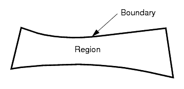
tree, and has its own properties and pop-up menu. The figure below shows a simple region where the lines surrounding the
region represent the boundaries. In this example, the region could be surrounded by a single boundary or multiple boundaries. The choice depends on what conditions and values need be assigned.
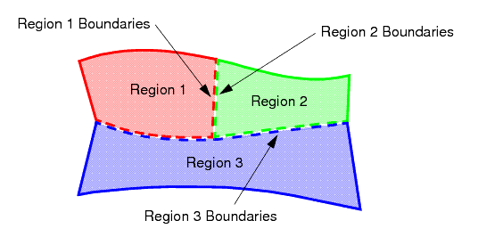
The discretization of a boundary corresponds to the surface bounding the volume mesh for the region. Boundaries are never shared between regions; a boundary can belong to only one region. The figure below shows an example of three separate regions. The dotted lines represent the boundaries that separate each region. The boundaries at the interface of one region and its neighbor are coincident in space.
Boundaries are created by:
- Volume mesh import or surface mesh import;
- Interface creation
- Boundary splitting
Only boundaries that belong to a surface mesh can be deleted.
Each boundary is given a unique name during the mesh import process, but it can be renamed, unless it is of the interface type.
Boundary Properties
| Index | Index reference for boundary (read only). This index is available through the Boundary Index field function. | |
| Interfaces | The interfaces that were created from this boundary (read-only). Blank if this boundary has not been in any interface creation. | |
| Part Surfaces | Specifies the surfaces included in the boundary, using the parts selection dialog. | |
| Type | The boundary type. The full list of possible boundary types is listed below, but the actual list you will see depends on the models you have selected. The list of types changes depending on whether the boundary is a regular one, or one created by an interface. | |
Axis


|
The axis of an axisymmetric region. The two icons are for a fluid and solid region respectively. | |
Flow Split Outlet

|
A flow split outlet boundary. | |
Free-Stream

|
A free-stream boundary. | |
Mass Flow Inlet

|
A mass flow inlet. | |
Pressure Outlet

|
A pressure outlet. | |
Stagnation Inlet

|
A stagnation inlet. | |
Symmetry Plane

|
A symmetry plane. | |
Velocity Inlet

|
A velocity inlet. | |
Wall

|
A wall. | |
Displacement

|
A solid stress displacement boundary | |
Traction

|
A solid stress traction boundary | |
Fixed

|
A solid stress fixed boundary | |
Free

|
A solid stress free boundary | |
Pressure

|
A solid stress pressure boundary | |
Normal Displacement

|
A solid stress normal displacement boundary | |
Force

|
A solid stress force boundary | |
| The list of possible types, and the icons, for boundaries generated by interfaces are listed below. | ||
Baffle


|
Generated from a baffle interface. | |
Contact


|
Generated from a contact interface. The two icons are for the primary and secondary boundaries respectively. | |
Fan


|
Generated from a fan interface | |
Fully Developed


|
Generated from a fully developed interface. | |
Internal Interface


|
Generated from an internal interface. | |
Porous Baffle


|
Generated from a porous interface. | |
Mixing Plane


|
Generated from a mixing plane interface. | |
| Parent Interface | The name of the interface that created the boundary for internal use (read-only). Only available on a boundary created by an interface. | |
Boundary Pop-Up Menu
| Highlight | Highlights a region in a scene. This option is only available if the scene is open. | |
| Edit... | Opens the table editor, which combines the functionality of the simulation tree and Properties window. It displays the selected region, all of its child nodes, and their properties in a single dialog. | |
| Create Interface | Creates an interface of a particular topology as defined in the submenu. The topology can be changed after creation. | |
| In-Place | Creates an in-place interface. | |
| Periodic | Creates a periodic interface. | |
| Repeating | Creates a repeating interface. | |
| Indirect | Create an indirect interface. | |
| Create Shell Region | Creates a shell region from the selected boundary. | |
| Combine | Executes the combine boundaries action to combines two or more boundaries into one. This is only active when more than one boundary is selected. | |
| Fuse... | Executes the fuse boundaries action to fuse the boundaries together. The selected boundaries from the tree are placed in the Selected list of the Fuse Boundaries dialog. | |
| Split Non-Contiguous | Executes the split non-contiguous boundary action to split non-contiguous boundaries (which may not be contiguous in space), into multiple boundaries each of which are contiguous. This will operate on all selected boundaries. | |
| Split By Angle... | Executes the split boundary by angle action to allow you to split a boundary based on the angle between adjacent faces. All the selected boundaries from the simulation tree are placed in the Selected list of the dialog. | |
| Split By Function... | Executes the split boundary by function action to split a boundary based on the value of a field function. All the selected boundaries from the tree are placed in the Selected list of the Split Boundaries by Function dialog. | |
| Split by Patch... | Executes the split boundary function action to split a boundary based on the underlying patch definitions of the surface mesh. This function can only be used if more than one patch definition exists in the imported surface. | |
| Split Interactively... | Executes the split boundary function action to split a boundary interactively in the current scene. A scene must be open for the option to be active. | |
| Project to Plane... | Executes the project boundary to plane action allowing you project a boundary onto a user-defined plane. All the selected boundaries from the tree are placed in the Selected list of the Split Boundaries by Function dialog. | |
| Solution | Applies operations in the submenu to the individual region. | |
| Clear | Executes the clear region solution action. Unavailable for Finite Element physics models. | |
See also: common menu items.