Setting Up a Compression Molding Simulation
Compression molding is a common production processes using polymeric, plastic, or composite parts. The initial charge can contain short or long fibers to produce short-fiber reinforced composites or sheet molding compounds (SMC). Compression molding is modeled with the Partial Fill and Free Surface models. The simulation starts with an initial charge of polymer placed in an open, heated cavity. The cavity is then closed and compressed to force the material to fill the cavity.
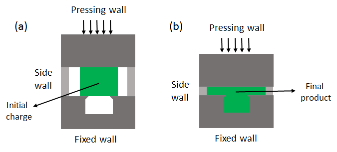
As shown in the figure, there are three main boundaries used in the process:
- Pressing wall: This boundary moves to press the initial charge into the mold.
- Side walls: This boundary adjusts in response to the motion of the pressing wall.
- Fixed wall: This boundary is fixed and often has many of the details of shape needed in the final product.
To set up a compression molding simulation:
-
For the physics continuum of the molded material, which can be a generalized Newtonian fluid, a viscoelastic fluid, or a short-fiber suspension, select the following models:
Group Box Model Time Implicit Unsteady Flow Viscous Flow Optional Models Adaptive Time-Step Optional Models Partial Fill Free Surface Free Surface -
Select
and specify the initial filling of the charge.
- Include enough charge to ensure that the cavity is filled at full compression.
- Start the simulation with the charge touching both pressing and fixed walls.
- Set the CFL number to be small enough to provide a stable and accurate simulation. is required for most applications.
-
Edit the
node and set the following boundary conditions:
- Pressing wall:
Boundary type: Wall
Physics Conditions Node Property Value Morpher Specification Specification Displacement Morpher Displacement Specification Specification Internal Moving Boundary Option Option Velocity Vector or Displacement Vector Select the node and specify the velocity or the displacement of the moving wall boundary.
- Side wall:
Boundary type: Wall
Physics Conditions Node Property Value Morpher Specification Specification Constraint Morpher Constraint Specification Constraint - For a curved wall: Initial Boundary
- For a flat wall: Boundary Plane
In some cases, the fluid can be forced out through the side boundary of the mold. In these situations, use the Free Stream condition instead of the Wall condition for the side wall. Note that the morpher conditions remain the same as in the preceding table.
The solver is not suitable for solid or metal forming applications.
- Fixed wall:
Boundary type: Wall
Physics Conditions Node Property Value Morpher Specification Specification Fixed Shear Stress Specification Specification Slip
- Pressing wall: