Extrusion and Free Surface Flow
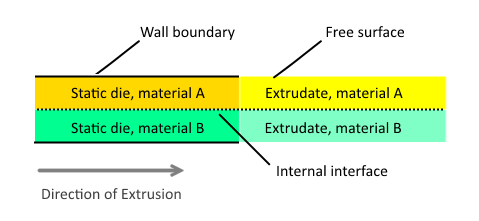
You can use the Free Surface model to simulate extrusion processes of polymer melts and other processes involving free surface flow of generalized Newtonian and viscoelastic fluids. A free stream boundary represents the outer surface of the extrudate, and an internal interface identifies the boundary between extrudates in contact. Since its shape is not known at the start of the simulation, the free surface is calculated as part of the solution. Typically, you set up these simulations as steady-state. You can also use time-dependent simulations, in which case the free surface position propagates at the material velocity.
STAR-CCM+ employs an Arbitrary Lagrangian-Eulerian (ALE) approach [187] to calculate the free surface of a polymer. The ALE method models the free surface through a mesh boundary that deforms depending on the shape and position of the free surface. This mesh motion is performed through the mesh morpher. You must provide appropriate boundary conditions and constraints for the mesh motion. The mesh motion is performed in steady-state that reaches an equilibrium shape and position when the solution converges.
The Free Surface model is the preferred approach when the approximate position of the interface between phases is known, so you can specify the initial interface position between multiple regions and use ALE to compute the final position. The Free Surface model is also useful in situations where the materials contact each other after the die lip.
You prepare a multi-part mesh using at least two parts for each extrudate. One part represents the static die or fixed geometry and the other part represents the extrudate or free surface. If you use the Line Kinematic condition, which is the default, the volume mesh of the free surface must be a directed mesh that is directed in the direction of the extrusion. You generate the mesh for the free surface in its initial undeformed state. For the Line Kinematic condition, the initial free surface mesh must be aligned with the direction of extrusion.
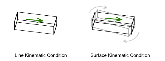
Kinematic Conditions
The Kinematic Condition setting puts constraints on cells in regions with Free Surface boundaries, limiting the ways that the cells can move and change shape on the faces of a Free Surface boundary. The Line Kinematic Condition applies only in cases of directed meshing, whereas the Surface Kinematic Condition uses all mesh types but is less appropriate for corners in extrudate regions.
The Line kinematic condition requires every edge of the boundary to be initially aligned with the extrusion direction, either parallel or orthogonal to it. This requirement does not hold for the die in either normal or inverse extrusion. Thus, the cell surfaces that are part of the free surface are always tangent to the stream velocity.
The Surface kinematic condition is less restrictive. It requires the free stream cell faces to be tangent to the stream velocity, but it does not require cell edges to be parallel to the velocity. Thus, a cell can rotate with respect to the velocity as long as the free stream surface remains tangent to the velocity.