Setting Up a Film Casting Simulation
Film casting is modeled as a free-surface flow with a two-dimensional mesh, for a thin film of one or more layers of viscoelastic fluids extruded into free space.
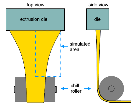
The figure below shows a typical case. The film flows into the simulated area at the top and out at the bottom. The edge is a free surface. Only half of the film between the die and the roller needs to be simulated, through the use of a symmetry plane running down the middle.
The thickness of the film is negligible, allowing for use of a two-dimensional mesh. The shape of the film is modeled, but the shapes of the die and roller are not included in the simulation.
To set up a film-casting simulation.
-
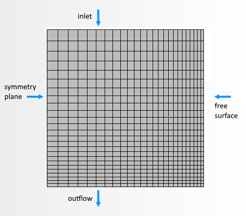
Create a two-dimensional mesh of the film, with edges designated as inlet, outflow and walls or symmetry planes. Use relatively small cells where velocity gradients will be steep, such as the free surface and the outflow. The following figure shows the film before deformation.
-
In the physics continuum, select the following models:
Group Box Model Time Steady or Implicit Unsteady Flow Viscous Flow Optional Models Two Dimensional Polymer Displacement Free Surface Optional Models Film Casting - Edit the node and set the Free Surface Properties to specify the direction of flow.
-
If the film consists of multiple layers, create a Layer
node for each layer:
- Edit the node and set Type to Velocity Inlet.
- Edit the node and set Type to Free Surface.
- Edit the other nodes under node and set Type for each to Free Stream or Symmetry Plane. The boundary for the outlet must be Free Stream.
-
Edit the node and set the values for Velocity and Film
Thickness. If the film consists of multiple layers,
specify the thickness for each layer:
See Boundary Settings.
-
Edit the
node and the value for
Method to
Traction Velocity or
Normal Velocity.
For Traction Velocity, the velocity component normal to flow is set to zero; for Normal Velocity, the force component normal to flow is set to zero.With either method, the node appears.
- Edit the node and select the value for Method.
-
Edit the
Physics Condition nodes for the free surface and set the following:
Node Property Setting Morpher Specification Specification Displacement Morpher Displacement Specification Specification Internal
- In the physics continuum, select Viscous Energy from the Optional Models box .
- Edit the node and set the Value property.
- For the side boundaries, edit the node and set Condition property. In most cases, since the film thickness is small, use Adiabatic.
- Edit the node and set Option, most commonly to Convection & Radiation.
- Edit the node and set the values for Ambient Temperature, Heat Flux, Heat Transfer Coefficient, and Surface Emissivity.
-
Run the simulation.
The mesh morphs in response to the difference between inflow and outflow velocities:
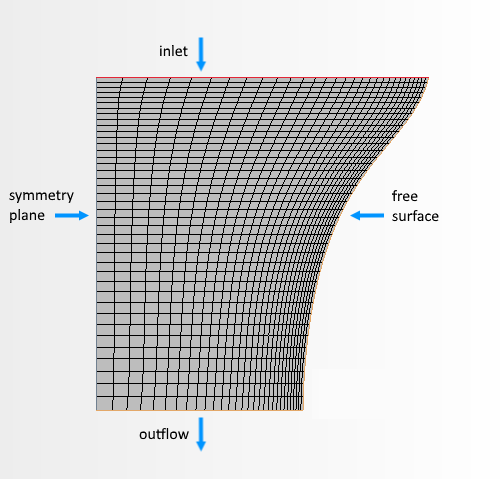
The simulation calculates film thickness, temperature, velocity, and stress profiles over the film.