Setting Up Co-Extrusion
Co-extrusion is extruding two or more materials in contact with each other, for example when an object and its coating are extruded together. The materials must be defined separately, then related to each other by specifying the interface between them.
Make the aspect ratio of the mesh as close to 1 as possible, to promote convergence.
For stable solutions, the material properties of the extrudates must be reasonably comparable. Make sure, for example, that dynamic viscosities are within an order of magnitude of each other. Similarly, keep the shear rate, Reynolds number, and relaxation time within comparable scales.
To set up co-extrusion:
- Create a separate region and a separate physics continuum for each extrudate.
- Create an interface between the boundaries of contact between the extrudates.
- Select and set Type to Internal Interface.
- Edit
and set the following properties:
Node Property Setting Morpher Specification Specification Displacement Morpher Displacement Specification Specification Internal - If the fluids inside the die are immiscible, select
and set
Option to
Unaligned. This allows cells to move in a direction parallel to the extrusion direction.

- When dealing with two or more materials inside a single die or channel, select and set Method to Slip.
- Expand
and set the following properties:
Node Property Setting Morphing Morphing Order Motionwise Morphing Method BSpline  BSpline Parameters
Linear Fitter Activated. See the Linear Fitter Option. - To prevent the morpher from overshooting along the symmetry plane, apply a non-zero morpher Damping Factor, typically 0.05–0.1.
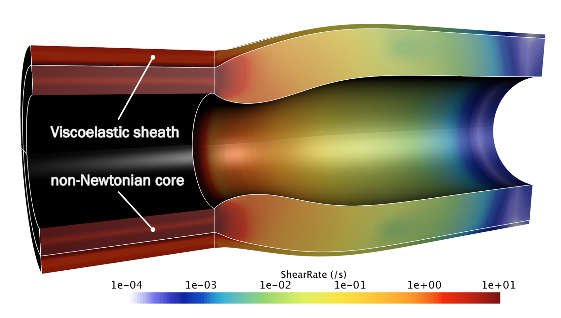
The figure below shows an example of co-extrusion, with the extrudates for a hose and sheath in contact. Note that the two extrudates use different physics models.