Overset Mass Conservation
Due to interpolation at overset interfaces, mass is not conserved. Two methods are provided that mitigate this resulted mass imbalance—the flux correction method, and the mass tracking method.
Flux Correction
Flux Correction is only available for single phase flow with the segregated solver. With this approach the sum of mass fluxes through whole collection of faces that connect acceptor cells to active cells (acceptor-to-active faces) is enforced to be zero. That is, the total mass flux across such connecting faces of all participating regions must be equal to zero.
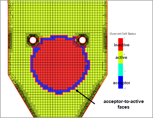
After the hole-cutting process, the acceptor-to-active transition faces are shown as follows:

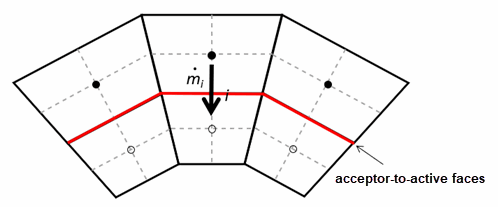
where is the mass flux through the acceptor-to-active face as illustrated below:

The mass flux correction defined in Eqn. (111) ensures that the sum in Eqn. (110) is zero. A divergence-free flow field is obtained.
Mass Tracking
The mass tracking option is available for single phase flow with both the segregated and the coupled solver as well as for VOF multiphase flow, which is solved by the segregated solver.
The mass tracking method is specifically designed for high compression situations like internal combustion engines where overset conservation errors are larger and accumulate over time. This method is not limited to high compression simulations—you can also use it in low compression simulations.
In contrast to the flux correction applied to the overset interface, mass balance is tracked within the simulation domain—in both background and overset regions. The mass conservation is enforced by adding source terms to the conservation equations. The source term calculation in the continuity equation Eqn. (664) is used as an example.
For each cell, the mass correction is proportional to the current mass existing in the cell. In most applications, the initial total mass is regarded as the reference mass. The correction mass is derived as follows:
For each cell, the source term is then given by:
- is the cell volume.
- is the density.
For multiphase flows the source term is added only to the cells having a sufficient volume fraction of the heavy fluid phase.