Visualizing the Water Film
Create three scalar scenes to visualize the water flowing down the inclined plane. One scene displays the film thickness in the fluid film regions and the second scene displays the surface of the rivulet volume in the VOF region. The third scene displays both the fluid film and VOF components.
-
Create an isosurface with a volume fraction value of 0.5 that represents the VOF resolved water film surface:
Create the scalar scenes.
- Right-click the Scenes node, and select .
- Select the Scalar Scene 1 node and then set Mesh Override to Show All Meshes.
-
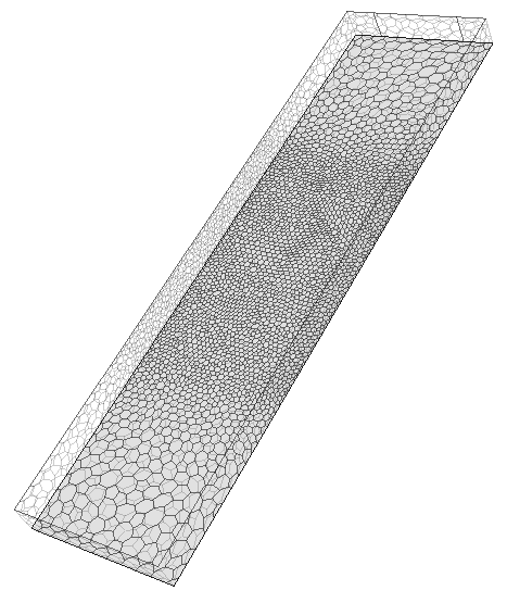
Manipulate the scene to make the mesh orientation similar to the example below:

- Use the Copy and Paste features to create two more copies of Scalar Scene 1.
- Rename the scalar scenes as Fluid Film Scene, Resolved Water Scene, and Combined Scene.
Set up the first scalar scene to display the film thickness.
-
Select the
Fluid Film Scene node and set the following properties:
Node Property Setting Fluid Film Scene Mesh Override Use Displayer Property  Scalar 1
Contour Style Filled Display Mesh Enabled  Parts
Parts
Parts  Scalar Field
Function Fluid Film Thickness  Color Bar
Orientation Vertical Position [0.05, 0.1]
Set up the second scalar scene to display the mesh outline of the resolved rivulet in the VOF region.
-
Select the Resolved Water Scene node and set the
following properties:
Node Property Setting Outline 1 Opacity 0.6 Color Mode Constant  Mesh Color
Mesh Color Sky Blue  Parts
Parts
Parts
Set up the third scalar scene to display both the liquid film and VOF components.
-
Select the Combined Scene node and set the following
properties:
Node Property Setting Outline 1 Opacity 0.6 Color Mode Constant  Mesh Color
Mesh Color Sky Blue  Parts
Parts
Parts Scalar 1 Contour Style Filled  Parts
Parts
Parts  Scalar Field
Function Fluid Film Thickness  Color Bar
Orientation Vertical Position [0.05, 0.1] - Save the simulation.