Setting up a Monitor
Create a monitor to visualize the water-air interface at a particular location within the test section.
By default Simcenter STAR-CCM+ produces a residuals plot that you can use to monitor the convergence of the solution. Additionally it is useful to create other monitors to help in assessing the progress of the simulation. In this tutorial, you monitor the height of the water-air interface where it enters the horizontal region of the test section.
To set up a monitor:
-
Right-click the Derived Parts node and select .
The Create Plane Section dialog appears in the Edit window.
- In the Input Parts box, make sure that PWR_2D is selected.
- Set the Origin coordinates to [2.15, 0.0, 0.0] m.
- In the Display box, select No Displayer.
-
Click
Create and then
Close.
Simcenter STAR-CCM+ creates a new derived part, Plane Section.
The location of the new plane section is indicated in the screenshot below.
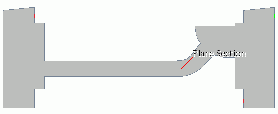
Before you can create the monitor, you create the report upon which the monitor is based. In this simulation, the height of the water-air interface is defined as the line integral of the volume fraction of water on the derived plane section. To monitor this value, you create a Line Integral report.
- Right-click the Reports node and select .
A new report is created named Line Integral 1, which is used to monitor the water volume fraction. Give the report a more suitable name.
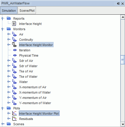
- Rename the Line Integral 1 node to Interface Height.
- Select the node and set Field Function to .
- Set Parts to .
-
Right-click the
Interface Height node and select
Create Monitor and Plot from Report.
The Interface Height Monitor and Interface Height Monitor Plot are added to the simulation tree.
- Save the simulation.