Dynamic Switching between Wall and Overset Boundary
Use dynamic overset behavior for overset mesh applications where an automatic switch from a wall boundary type to an overset boundary type or vice versa is required.
Examples for such applications are:
- Closely counter-rotating objects such as screw pumps
- IC engine piston motion where the cylinder has a variable radius
The dynamic overset behavior is an option that is available for wall boundaries after an overset mesh interface is created. When activated, the dynamic overset option lets a wall behave as either a wall boundary or as an overset boundary depending on whether it intersects another overset region or not.
On a wall boundary, you set the property Allowable Overset Face States, that controls which cell types the overset hole-cutting algorithm can assign to cells adjacent to the boundary. For regular wall boundaries, do not change to overset boundaries, this property must be set to Active, Inactive. When the cells next to the wall participate in the flow solution, their state is Active. When the hole-cutting algorithm determines that they lie outside the zone of flow, their state is Inactive.
Simulations in which the wall boundary must conditionally change to an overset boundary generally require the Active, Acceptor behavior.
There are two main scenarios for this option:
- Overlapping overset regions without a background mesh
- A wall boundary of the overset region sliding on a wall boundary of the background mesh
Overlapping overset regions without a background mesh
When you activate the dynamic overset behavior to model a scenario without a background mesh, the hole-cutting process checks whether a boundary face resides inside or outside any of the other overset regions. If the hole-cutting process detects that a boundary face lies within another overset region, the cells that are adjacent to the boundary become acceptor cells. The previous wall boundary becomes an overset boundary or the overset boundary becomes again a wall boundary depending on position.
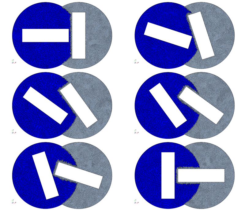
The following diagram shows two counter-rotating square objects. The objects are embedded within two overset regions. There is no background mesh present.
To ensure the boundaries to be used as overset boundaries, the two outer walls are set to dynamic overset behaviour: Active, Acceptor.

After initializing the overset interface between these two regions, the overlapping wall acts like an overset boundary, around which the cells are marked as acceptor cells dynamically.

Overset boundary sliding on the background mesh
When you activate the dynamic overset behavior to model a scenario with a background mesh, the hole-cutting process checks whether the moving wall boundary of the overset region still coincides with the wall boundary of the background mesh. If the hole-cutting process detects that a wall boundary face of the overset region no longer coincides with a wall boundary face of the background region, the cells that are adjacent to the boundary become acceptor cells. The previous wall boundary of the overset region becomes an overset boundary. If such an overset boundary moves so that it coincides with a background region wall boundary, it reverts to a wall boundary.
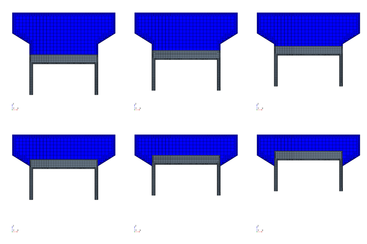
The following screenshot shows an example application—the translational motion of a simplified piston within a cylinder of variable radius. The overset region requires the overset topology option Piston with the direction setting +Z. The sliding wall of the overset region requires the dynamic overset behavior Active, Acceptor.
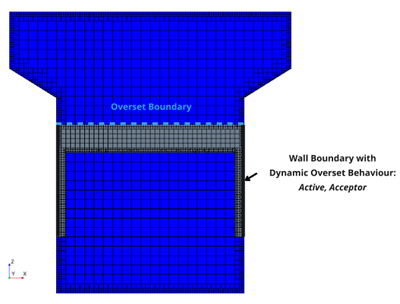
After initializing the overset interface to execute the hole-cutting process:
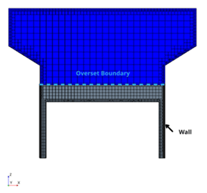
Here, the overset region (gray), that is, the piston is in its initial position. The side wall boundaries of this overset region coincide with the side wall boundaries of the background region (blue), which is the cylinder. You must set up the sliding side walls of the piston as a wall boundary (and not as an overset boundary), because if part of the overset region boundary coincides with the boundary of the background region, that part must be of the same boundary type as the background region. The dynamic overset option for the wall boundary is set to Active, Acceptor, because the wall boundary of the overset region behaves as an overset boundary when it slides out of the wall boundary of the background region.
The piston moves upward. The following screenshot shows the mesh after the piston moved upwards.
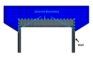
The upper part of the side boundary of the piston no longer coincides with the wall boundary of the background mesh. The dynamic overset behavior automatically detects this situation and changes the previous wall boundary to an overset boundary. The lower part of the side boundary that still coincides with the wall boundary of the background region remains a wall boundary.
Artificial Thickening for Thin Structures
You are generally advised to generate meshes for the overset and the background regions with similar cell size distributions on both meshes. Therefore, when you simulate a thin geometrical structure within a background or overset region, for example a thin flap or a baffle, together with a comparatively larger geometrical structure in the corresponding overset or background region, you are required to resolve the large geometrical structure with a mesh of a similar cell size as the thin structure. This overset requirement can lead to high cell counts. If this requirement is not fulfilled, that is, there is a difference in mesh resolution of the background mesh and the overset mesh, the hole-cutting algorithm can face problems and lead to unexpected results.
When you apply the Active dynamic overset option to the wall boundary of the thin structure, this requirement is relieved and you can maintain a discrepancy in cell sizes on both meshes. You specify a number of protective layers around the thin structure to thicken it artificially. The number of layers should be such that the total thickness of the layers approximately matches the cell size of the coarse mesh of the other region.
The boundary remains a wall boundary and the cells that are adjacent to the boundary are always active.
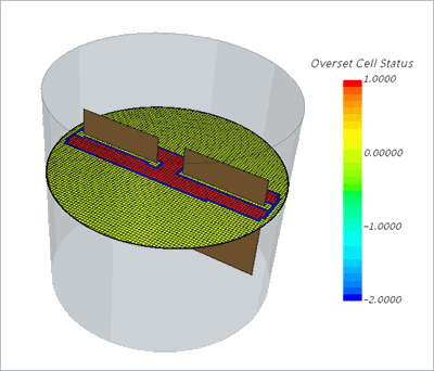
You see two baffles within a large vessel that is colored with the overset cell status of the background mesh. The baffles are each modeled inside two overset regions and the vessel is the background region. For the wall boundaries of the baffles, the Allowable Overset Faces States is set to Active. This setting is required to ensure that the baffle is recognized as internal object with a wall boundary. One protective cell layer is specified. The overset cell status for the cells that are adjacent to the boundary is 0. This status corresponds to an active state of the cells in the background mesh