Porous Baffle
There are situations when the porous medium thickness is small compared to the other dimensions, for example, the flow through a perforated plate or a wire screen. As a result, the flow resistance and heat transfer can be assumed to be one-dimensional. The treatment of the flow resistance is similar to porous media.
where:
- is the superficial velocity normal to the surface
- is the porous inertial resistance
- is the porous viscous resistance
The coefficients and effectively define the baffle permeability for one-dimensional flow. The method assumes that the direction of the flow is unchanged as it passes through the baffle.
- conduction is one-dimensional
- thermal inertia is negligible
- the effective baffle area for heat conduction is given by
- is the surface porosity that is defined as the ratio of the area of the holes to the area of the surface
- is the temperature difference in the fluid on either side of the baffle
- are the heat transfer coefficients on either side of the baffle
- is the thermal resistance per unit area
- is the thermal conductivity of the baffle
- is the mass flow rate
- is the fluid enthalpy
where and are the conductivity and thickness, respectively, of each of the layers comprising the baffle.
Assuming that the turbulence generated from a resistance-based porous baffle dominates the turbulence reaching it, the turbulent quantities on the downstream side of the porous baffle are approximated using:
where:
- is the magnitude of the slip velocity at the baffle (where and are the baffle velocity and the superficial velocity of the fluid at the baffle respectively).
- is turbulence intensity.
- is the turbulence length-scale.
- is the model coefficient in Eqn. (1214).
Tangential Momentum Balance
The hydraulic behaviour of a baffle can be characterised by a three-dimensional resistance tensor:
Denote the local coordinate axis normal to the baffle as . The component is the normal hydraulic resistance of the baffle, and the components and are lift coefficients, that is, they are responsible for the pressure drop across the baffle as a result of the flow parallel to the baffle. Assuming a no-lift scenario, can be split into the normal coefficient of resistance and a two-dimensional tensor:
Hereafter the subscript || denotes the two-dimensional manifold tangential to the baffle.
To simplify the model further, it is assumed that the tensor is isotropic. Therefore, the equation for the resistance tensor reads:
To formulate conditions at the interface, consider a row of cylinders as shown below. The control volume is bounded by the dashed lines. Initially, it is assumed that the control volume has a finite thickness and the interface conditions are obtained as a limit when it shrinks to zero.
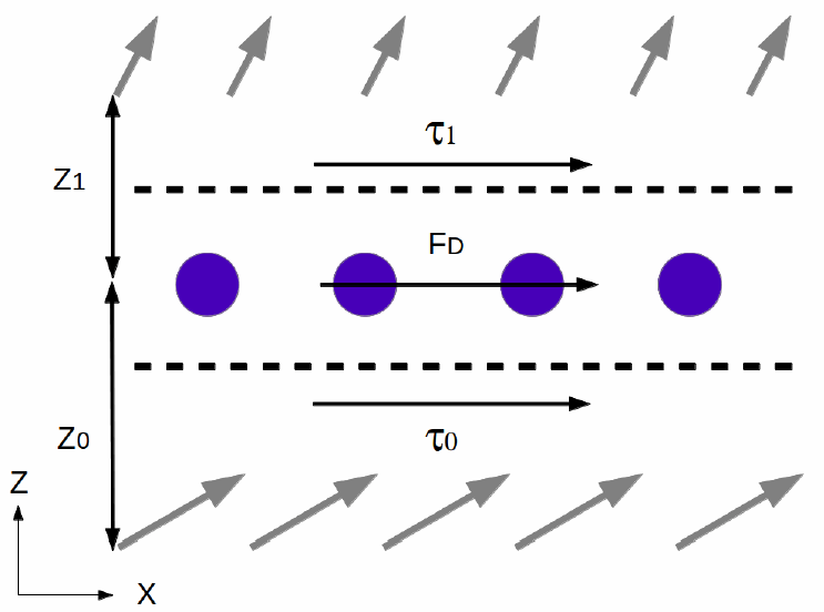
There are three forces acting on the control volume: two shear stresses , , and the drag force :
where is the velocity of the baffle and is the surface area of the porous baffle interface.
Assuming that
the force balance can be written as
Where is the velocity at the interface and is the effective viscosity.
The flow field near the baffle depends on the tangential resistance. If the tangential resistance is 0 and the viscosity at two sides of the baffle are equal, Eqn. (1867) yields:
and the tangential component of the velocity retains continuity and smoothness across the baffle.
Alternatively, for , the LHS of Eqn. (1867) can be neglected and the baffle effectively imposes non-slip conditions at the interface:
Tangential Phase Resistance
Considering the expression for the drag force above (Eqn. (1865)), in the case of multiple phases :
where:
- is the phasic density
- is the phasic velocity
- is the phasic tangential inertial resistance
- is the phasic tangential viscous resistance
The phasic tangential resistance values are obtained in the same way as the values for phasic normal resistance, but in this case is the porous inertial tangential resistance and is the porous viscous tangential resistance. The values for and are specified by the user.