Loading the Starting File and Setting Up Physics

For this tutorial, you are provided with a starting simulation that contains predefined mesh operations that generate a structured volume mesh. This type of mesh is suitable for turbomachinery applications..

In the starting simulation, you define the physics continuum for the compressible air, the boundary conditions, interfaces, and the rotor stage motion. The prepared simulation is the reference simulation for the Design Manager project.
For the preparation of the reference simulation, you can load the starting file in serial. You specify the number of cores running the designs at a later stage:
  1. Open a double precision version of Simcenter STAR-CCM+ and select File > Load.
  2. In the Load a File dialog:
    1. Set Process Options to Serial.
    2. Click Browse.
    3. In the Open dialog, navigate to the designExploration folder of the downloaded tutorial files and select the file Stage37_smartsweep_start.sim.
    4. Click Open, then OK.
In the simulation, you model air as a compressible Ideal Gas.
  1. For the continuum, right-click the Continua > Physics 1 > Models node, select the following models in order:

    Group Box

    Model

    Space

    Three Dimensional

    Time

    Steady

    Material Gas
    Flow

    Coupled Flow

    Gradients (Selected automatically)

    Equation of State

    Ideal Gas

    Energy Coupled Energy (Selected automatically)

    Viscous Regime

    Turbulent

    Reynolds-Averaged Navier-Stokes (Selected automatically)

    K-Omega Turbulence

    SST (Menter) K-Omega (Selected automatically)

    Wall Distance (Selected automatically)

    All y+ Wall Treatment (Selected automatically)

    Optional Models

    Cell Quality Remediation

    Solution Interpolation

The compressible air flow is constrained with a stagnation inlet and a mass flow outlet. As you only model a sector of the air compressor, you set the upper and lower boundaries to Symmetry Planes and create periodic interfaces for the rotor and stator regions, respectively. The interface between the rotor and the stator is a mixing plane interface.

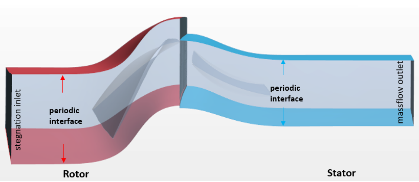
The region topology and interface settings are shown below:


  1. To set the boundary conditions:
    1. Select the Regions > RotorPassage > Boundaries > Inlet node and set Type to Stagnation Inlet.
    2. To define the mass flow as a global parameter, right-click the Automation > Parameters node and select New > Scalar.
    3. Rename the Scalar parameter to massflow and set its properties as follows:
      Properties Values
      Value 0.448
      Dimensions Mass/Time

      According to the stage 37 air compressor performance data, this mass flow value corresponds to a known stable point on the speedline curve around the choke area.

    4. Select the StatorPassage > Boundaries > Outlet node and set Type to Outlet.
    5. Select the Outlet > Physics Values > Mass Flow Rate node and set Value to ${massflow}.
  2. To define the interfaces:
    1. Multi-select the Interfaces > RotorPassage/RotorPassage and StatorPassage/StatorPassage nodes, right-click and select Edit.
    2. In the Multiple Objects dialog, set Topology to Periodic.
    3. Select the RotorPassage/StatorPassage node and set Type to Mixing-Plane Interface.
      For more details, refer to Mixing Plane Interface.
  3. You set a moving reference frame for the rotor region. Moving reference frame provides a time-averaged solution for a rotating object. In this way the simulation can run steady without considering the transient effect and moving the mesh vertices. To define the rotation of the rotor, you create a rotating reference frame:
    1. Right-click the Tools > Reference Frames node and select New > Rotating.
    2. Select the Rotating node and set the properties as follows:
      Properties Values
      Axis Direction [0.0, 0.0, 1.0]
      Axis Origin [0.0, 0.0, 0.0]
      Rotation Rate 1800 radian/s
    3. To assign the rotation to the rotor region, right-click the Regions > RotorPassage > Physics Values > Motion Specification node and set Reference Frame to Rotating.
  4. Save the reference simulation as Stage37_smartsweep_ref.sim