Coupling Coil Regions with Coil Circuit Elements
Simcenter STAR-CCM+ allows you to couple 2D or 3D excitation coil regions with the excitation coil elements of a 1D electric circuit.
- Define the excitation coil region and physics continuum as described in the previous sections.
-
In the physics continuum associated with the coil region, select
Circuit Model from the
Optional Models group box.
- When the physics continuum contains either the Finite Element Magnetic Vector Potential model or the Transverse Magnetic Potential, also select the Excitation Coil Lumped Parameter model, which extracts the lumped parameters (that is, resistance and inductance) of the excitation coil region (see Extracting the Excitation Coil Lumped Parameters. The extracted lumped parameters are used to define the circuit element load (see Circuit Elements Reference).
-
Define the electric circuit as appropriate.
For more information, see Creating Electric Circuits.
To add an excitation coil element to the circuit:
-
Right-click the node and select .
Simcenter STAR-CCM+ adds the selected circuit element under the Circuit Elements node.
To associate the excitation coil circuit element with the corresponding excitation coil region:
- Select the node and set Regions to the relevant coil region.
When you associate an excitation coil region with a circuit element,
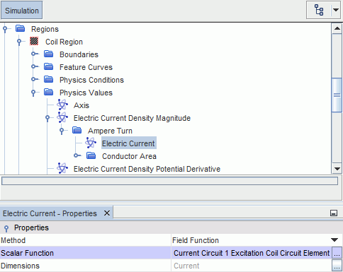
Simcenter STAR-CCM+ automatically sets the electric current in the coil region to the electric current computed by the circuit solver.


- If you wish to specify a different current for the coil region, change the settings for the relevant node, as desired.
-
Select the node and set Load Type to either
Compound or Voltage. The
available options depend on the magnetic vector potential model in use.
For more information, see Circuit Elements Reference.
The Excitation Coil Lumped Parameter model provides
reports for the coil magnetic inductance, magnetic flux linkage, and motion-induced
voltage (see Reports).
You can create each report individually from the Reports node or you can add all reports in one step from the coil circuit element. To add all reports:
- Right-click the node and select Create Reports.