Specifying the Coupled Region and Boundaries
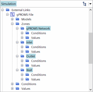
To export data to gPROMS, you couple the fluid region with the gPROMS network, and couple the inlet, outlet, and wall boundaries with corresponding gPROMS environment zones and surfaces.
By default, Simcenter STAR-CCM+ creates three zones—a volume zone that represents the gPROMS network and two surface zones that represent the gPROMS environment zones. For this tutorial, you require four zones—one zone for the region and three zones for coupling the inlet, outlet, and wall boundaries.
- Expand the node.
To couple the Simcenter STAR-CCM+ fluid region with the gPROMS network:
-
Select the node and set Parts
to SprayDryer.
The External Volume Part is automatically set to the external region that represents the gPROMS network.
To couple the Simcenter STAR-CCM+ inlet boundary with the corresponding
gPROMS environment zone:
-
Edit the node and set the following properties:
Node Property Setting Surface Parts Parts External Surface Part Parts (already selected)
To couple the Simcenter STAR-CCM+ outlet boundary with the corresponding
gPROMS environment zone:
-
Edit the node and set the following properties:
Node Property Setting Surface Parts Parts External Surface Part Parts
To couple the Simcenter STAR-CCM+ wall boundaries:
- Right-click the Zones node and select New.
- Rename the node to Wall.
-
Edit the node and set the following properties:
Node Property Setting Surface Parts Parts and Wall External Surface Part Parts 
- Save the simulation.