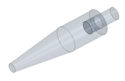
Creating the Cyclone Body
Create the main body and conical section of the cyclone separator geometry.
-
Create a sketch for the main body of the cyclone geometry:
-
In the Sketch panel, click
 (View
Normal to Sketch Plane).
(View
Normal to Sketch Plane).
-
To specify the distance between the grid lines on the sketch plane,
click
 (Set Sketch
Grid Spacing).
(Set Sketch
Grid Spacing).
-
Click
 (Create Circle) and
draw a circle centered on the origin (0,0).
(Create Circle) and
draw a circle centered on the origin (0,0).
-
In the Sketch panel, click
-
To form the main body, extrude the sketch:
- Right-click the Main Body Sketch node and select Extrude.
- In the Extrude panel, set Distance to 1.5*$D.
- Set Body Interaction to None.
- In the Extrude panel, click OK.
- Within the Body Groups node, rename Body 2 to Main Body.
-
To remove the volume occupied by the outlet pipe:
-
In the Subtract Bodies panel, to the
right of the Tool Bodies selection box, click
 (Open Selector).
-
Within the Select Tool Bodies panel, select
Outlet Pipe. Click (Close Selector).
-
In the Subtract Bodies panel,
activate the two options, Keep Tool Bodies and
Imprint.

-
In the Subtract Bodies panel, to the
right of the Tool Bodies selection box, click
For the conical section of the cyclone separator you prepare
two sketches and then apply a loft feature between them.
-
Extract the sketch from the bottom face of the main body part:
-
In the Vis toolbar, click
 (Make Scene
Transparent).
(Make Scene
Transparent).
-
In the graphics window, select the bottom face of the main body part:

-
In the Vis toolbar, click
-
Create a plane on which to sketch the base of the cyclone:
- Right-click the XY node and select .
- In the Plane By Transformation panel, click OK.
- Select the Plane 1 node and in the Properties window enter 4*$D for the Z component of the Translation Vector.
- Rename Plane 1 to Cyclone Base Plane.
- At the bottom of the 3D-CAD panel, click Update3D-CAD .
-
Draw the cyclone base:
- Right-click on the Cyclone Base Plane node and select Create Sketch.
-
In the Sketch panel, click (View
Normal to Sketch Plane).
-
Click (Create
Circle) and draw a circle around the origin.
- Right-click on the circle and select Apply Radius Dimension.
- In the Dimension dialog, enter 0.18*$D and click OK.
- In the Sketch panel, click OK.
- In the feature tree, rename the Sketch 1 node to Cyclone Base Sketch.
-
Create the body of the conical section using the loft feature:
- Select the Cyclone Base Sketch node, press and hold <CTRL>, and also select the FaceSketch 1 node.
- Right-click one of the nodes and select Loft.
- In the Loft panel, click OK.
- Rename Loft 1 to Conical Section Loft.