Prescribing Motion along a Specified Trajectory
Rotation and translation motions allow you to define the mesh motion by specifying the rotation rates, or rotation angles, along specified axes, and translational velocities. In some cases, it is convenient to define the rigid motion by specifying the mesh trajectory in space.
- When using a field function, the trajectory is described analytically with three components. For example, a circle with a radius is analytically described as .
- When using an imported table, Simcenter STAR-CCM+ interpolates the discrete positions to construct the
continuous trajectory in time. The direction along the trajectory is implicitly
determined by the order in which the set of coordinates are given in the table,
starting from the coordinates in the first table row. A trajectory table can
contain either of the following data:
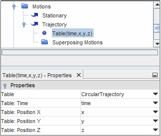
- values—In this case, you provide a table with four columns. One column contains time values, and three columns contain the corresponding coordinates that define the trajectory of the region in time.
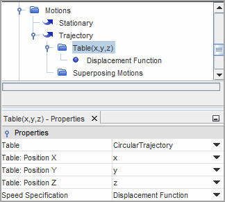
- values—In this case, you provide a table with three columns that contain the coordinates that define the trajectory. As this format does not provide the position of the region along the trajectory as a function of time, you also specify either the displacement or velocity of the region using a field function.
You follow the instructions to define a trajectory motion:
- Right-click the node and select .
-
Select the
node and set the following properties:
Property Setting Coordinate System Specifies the coordinate system with respect to which the discrete coordinates are specified. Managed Coordinate Systems Specifies one or more coordinate systems that follow the Trajectory motion. When adding superposing motions, Simcenter STAR-CCM+ handles the essential managed coordinate system to the parent motion automatically. Method Selects the method that you want to use to specify the trajectory. The available options are: - FieldFunction(x,y,z)—for
position values as function of time. You assign
three scalar field functions to the three trajectory
position components. This option is useful when you
have an analytical description for the trajectory
motion.
The field function method can not be used for the Constraint Rotation.
The right-click action Export Trajectory to VTK File is not available for this input method.
- Table(x,y,z)—for position values only.
- Table(time,x,y,z)—for position values at specified times.
- FieldFunction(x,y,z)—for
position values as function of time. You assign
three scalar field functions to the three trajectory
position components. This option is useful when you
have an analytical description for the trajectory
motion.
To specify a trajectory using field function:
- Right-click the node and select .
-
Define a scalar field function with respect to time for each position
component, for example
.

- Select the node and set the Method to FieldFunction(x,y,z).
-
Select the node and assign the corresponding field functions.

To import the tabular data:
- Right-click the node and select .
- In the Open dialog, navigate to the file containing either the or values and click Open.
After you imported the tabular data:
-
Depending on the table format, that you specify using the Method property for the
Trajectory node, complete the motion definition as
follows:
Table Format Steps Table(x,y,z) - Select the node.
- Specify the imported table and the columns that define the x, y, z positions by setting the corresponding properties.
- To specify the method
for defining the speed along the trajectory, set Speed Specification to either
Displacement Function or
Velocity Function, as appropriate.

- Depending on the speed specification method, select either the or Velocity Function node and set Scalar Function to the function that defines the displacement or velocity magnitude.
Table(time,x,y,z) - Select the node.
- Use the node properties
to specify the imported table and the columns that define the
time and x, y, z values.

Simcenter STAR-CCM+ allows you to visualize the motion trajectory in a scene using an arbitrary probe. To visualize the trajectory:
- Create the required scene.
- Right-click the node, select Export Trajectory to VTK File... then save the file to the desired location.
- Right-click the Derived Parts node and select .
-
For the arbitrary probe, set the following properties:
Property Setting Input Parts Select the moving region and its boundaries. Surface Input Option File File Select the VTK file containing the trajectory data. - Add the arbitrary probe part to the required scene displayer.
-
Optionally, you can add superposing motions. With superposing motions, the moving region translates along the specified trajectory and, additionally, rotates and translates as prescribed by the superposing motions.
For more information, see Superposing Rotations on a Trajectory Motion.