Boiling
The Wall Boiling and Bulk Boiling models within the Eulerian Multiphase framework of Simcenter STAR-CCM+ are aimed at forced-convection, subcooled, boiling applications.
In subcooled boiling, local boiling occurs on a heated surface despite the mean temperature of the liquid being less than the saturation temperature. The degree of liquid subcooling is expressed either as a temperature difference or an enthalpy difference below the saturation value.
Provided the flow regime near the wall remains close to bubbly flow, a standard subcooled boiling model can be pushed towards zero subcooling conditions (that is, saturated boiling). The model can also be pushed towards higher heat fluxes approaching Departure from Nucleate Boiling (DNB) conditions.
A successful wall boiling model predicts the amount of wall superheat, which is the amount the wall temperature exceeds the saturation temperature, as well as the axial and radial distribution of vapor. The Eulerian Multiphase framework is appropriate for modeling this kind of wall boiling process for the following reasons:
- By definition, the phases in subcooled boiling are not in thermal equilibrium and each phase requires its own energy equation.
- The phases in subcooled boiling require their own equation of motion, as the bubble moves away from the boiling surface while cool liquid moves to take its place.
- The condensation rate of vapor in the bulk subcooled liquid is a part of the wall boiling process and decides when net vapor generation first begins on the wall and how the vapor is distributed downstream of this point.
Both of these non-equilibrium flow features can be different in reality from predictions using equilibrium models.
Bulk Boiling
The Bulk Boiling model in Simcenter STAR-CCM+ is an essential part of subcooled boiling. Boiling and condensation is modeled in the interior of the flow, provided the rate of interphase mass transfer depends only on the following:
- The heat transfer rate from the liquid and vapor to a saturated interface between these two phases.
- The interfacial area density that is provided by a well-defined characterization of bubbles by their size and number density.
This means that the bulk boiling model is suitable for modeling vapor bubbles whose initial size and concentration:
- are already known as an inlet condition (or initial condition in the case of transient simulations)
- are estimated by a size distribution model (such as S-gamma or AMUSIG)
- are generated by the Wall Boiling model.
This thermally-driven model is not suitable for describing boiling without bubbles (homogeneous nucleation), evaporation (concentration-driven multi-component mass transfer), nor cavitation (inertially-limited mass transfer). The thermally-driven model is also unsuitable when the resulting interphase mass transfer rate occurs on time scales that are much shorter than that of the flow. This scenario is unlikely to be solvable with a segregated solver algorithm.
Wall Boiling
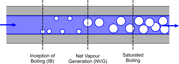
Small bubbles start to appear on the wall at the point of Inception of Boiling (IB). In this example, the degree of subcooling downstream of IB becomes smaller as the liquid heats up and the void fraction starts to grow from the point of Net Vapor Generation (NVG). Downstream of the point of NVG, the void fraction grows rapidly. Bubbles detach from the wall and move into the subcooled liquid. Some of these bubbles condense in the subcooled liquid, enhancing heat transfer to the liquid. Further downstream, the bulk liquid reaches the saturation temperature and saturated boiling begins.

The wall boiling process can be broken down into three stages that are based upon the different types of heat transfer, as illustrated in the diagram below. The dark blue line shows the surface available for heat transfer to occur across vapor/liquid (bubble) and solid/liquid interfaces.

The method for calculating each type of heat transfer is described below:
- Evaporation – Modeling of heat transfer at the wall begins with a prediction of the nucleation site number density. This value determines the number of bubbles per unit area, which is based on the amount of superheating in the fluid adjacent to the wall. This number density is used, along with the bubble departure frequency and bubble departure diameter to model the evaporative heat flux across the nucleation sites.
- Quenching – This occurs when buoyancy causes a bubble to leave the surface, liquid fills the space that the bubble occupied, enhancing heat transfer. The resulting heat flux is modeled using the quenching heat transfer coefficient. The area over which quenching takes place is the bubble influence wall area fraction.
- Convective Heating – After a bubble has detached and moved away from the wall, the remaining area is available for convective heat transfer. The wall dryout area fraction specifies how much convective heat transfers to the liquid phase and how much of it transfers to the vapor phase.
The evaporation and quenching mechanisms can support much higher heat transfer rates than single-phase, forced convection.