Reviewing the Results
-
To improve the residuals, you can turn off the normalization for the monitors.
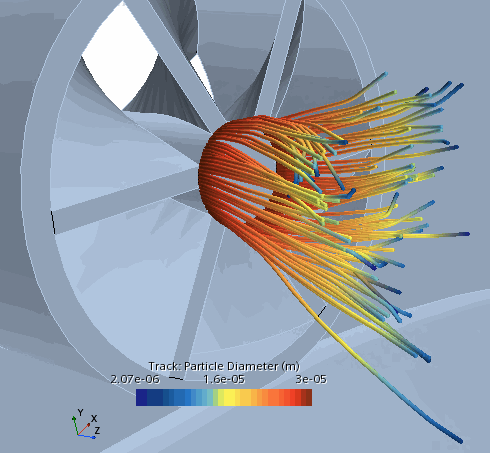
n-dodecane is a liquid fuel which enters the combustor as a spray of droplets which then evaporate before they combust. To optimize the efficiency of combustion, it is important to check that the fuel is evaporating effectively after entering the combustor. To visualize the droplets evaporating, you can track the particle diameter of the n-dodecane fuel droplets in a scalar scene.
-
Load the track file for the Lagrangian phase.
- Right-click the node and select Track File.
- In the Open dialog, select Spray_Combustion.trk and click Open.
-
Create a scene to view the diameter of the n-dodecane fuel droplets as they enter the fluid domain.
The droplets of fuel decrease in diameter as they evaporate and become fully vaporized soon after entering the combustor.
-
Open the
Temperature,
3D Flame, and
Soot scenes.
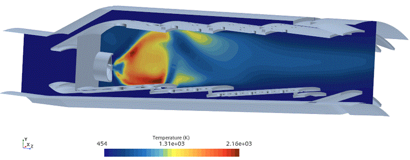
The temperature scene shows the temperature on a cross section of the fluid domain. You can see that the temperature is highest in the area immediately after the droplets have evaporated—where the fuel combusts.
The 3D flame scene shows the temperature of the entire volume of the fluid domain.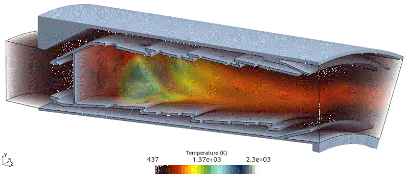
The soot scene shows that the highest level of soot 2 x 10⁻⁴ kg/m3) is located in the hottest area of the flame.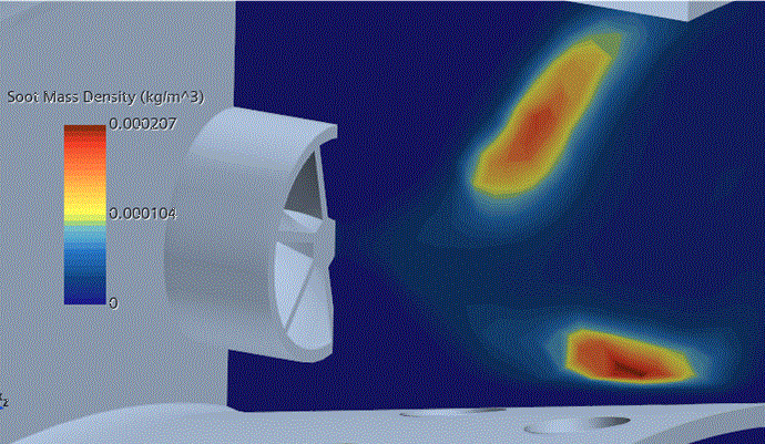
-
Open the following plots:
-
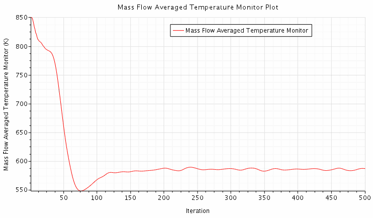
The average temperature at the outlet of the combustor in this simulation is less than 600 K. Industrial combustor simulations are likely to reach a temperature of around 1200 K at the outlet. The Mass Flow Averaged Temperature Monitor Plot is useful in showing that the simulation arrives at a steady temperature as it approaches convergence. -
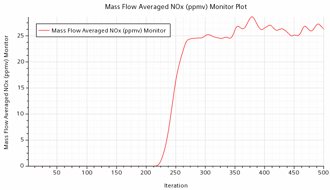
The solvers are set to begin solving for nitrogen oxide after 200 iterations, after which the mass flow of nitrogen oxide emissions at the outlet increases and fluctuates just under 25 ppmv. The custom field functions calculate the dry emissions corrected at 15% O2, as is common in industry. However, since the tutorial uses a simplified setup, the NOx levels in this simulation do not represent an industrial level. -
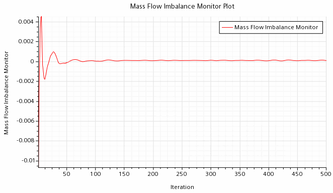
This report compares the mass flow at the inlet with the mass flow at the outlet and shows that the overall mass imbalance equalizes as the simulation converges.
-