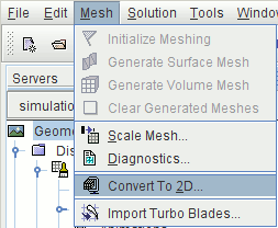
Converting the Mesh to Two-Dimensions
Simcenter STAR-CCM+ can use the surface of a three-dimensional mesh to create a two-dimensional mesh if the surface to be used lies on the X-Y plane at Z = 0.
-
Select from the menu.
-
In the
Convert Regions To 2D dialog, set the following properties:
Property Setting Delete 3D Regions After Conversion Activated Tolerance 1.0E-18 - Click OK.
Some work is now required to clean up the region and associated boundaries.
- Expand the Regions node and rename the fluid 2D node to Fluid.
-
Expand the
node to see the boundaries that remain after the conversion process.
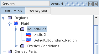
Combine these boundaries to form a single boundary and then split it into four separate boundaries:
- Multiselect the Default_Boundary_Region node and the cyclic 2 node.
-
Right-click and select
Combine.
There is now a single Default_Boundary_Region node.
-
Right-click the Default_Boundary_Region node and select
Split by Angle.
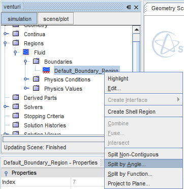
The default settings in the Split Boundaries by Angle dialog are sufficient. -
Click
OK.
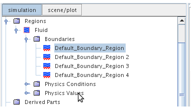
Four boundaries appear as shown below:
-
Rename the boundaries as follows:
Old Name New Name Default_Boundary_Region Axis Default_Boundary_Region 2 Outlet Default_Boundary_Region 3 Inlet Default_Boundary_Region 4 Wall At this stage, do not set the boundary types until you have selected the models for the analysis.
An additional physics continuum was created for the two-dimensional mesh during the mesh conversion process, which means that the original continuum for the three-dimensional mesh is not required.
- Delete the node.
- Rename the Physics 1 2D node to Physics 1.
- Save the simulation.