Setting Boundary Conditions and Values
Specify a constant velocity in the X direction at the inlet, and a constant pressure at the outlet. Set the centerline boundary to be of type axis. This axis boundary must lie exactly on the Y = 0 line; project the axis to the appropriate plane.
- Select the node and set Type to Axis.
-
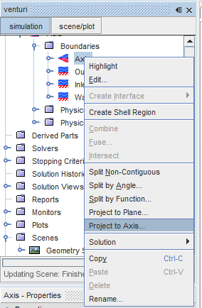
Right-click the
node and select
Project to Axis from the pop-up menu.

-
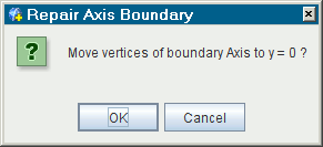
In the
Repair Axis Boundary dialog, click
OK.

The vertices move along the axis to Y = 0.
Specify conditions for the inlet and outlet boundaries:
-
Set the boundary types for the inlet and outlet:
Boundary Type Inlet Velocity Inlet Outlet Pressure Outlet -
Edit the
node and set the following properties:
Node Property Setting Physics Conditions 
Method Intensity + Length Scale 
Method Components Physics Values 
Value 0.034 
Value 0.0107 m 
Value [1.5, 0.0] m/s -
Edit the
node and set the following properties:
Node Property Setting Physics Conditions 
Method Intensity + Length Scale Physics Values 
Value 0.034 
Value 0.0107 m - Save the simulation.