Geometry Parts
A geometry part is a collection of surfaces and curves that you wish to address as one object. Parts surfaces and curves can be defined by CAD data or discrete (surface mesh) data, depending on the type of geometry part. A single object is referred to as a leaf-level part; a collection of geometry parts is referred to as a composite part. A surface can contain one or more sets of faces and a curve can contain one or more sets of edges.
Geometry parts provide an efficient way of organizing geometry data in preparation for meshing. Not all parts present in a simulation are required for a given meshing process. You can assemble a particular geometry combination by selectively assigning parts to regions.
Leaf-level parts can be combined to form composite parts, and composite parts can be exploded to their component parts.
Within a given composite part, the leaf-level parts must have unique names although these names can be reused in other composite parts.
Geometry parts, part surfaces, part curves, and part contacts, all have unique indices that you can use in field functions.
- Geometry Part Types
-
- The following parts are classified as leaf-level parts (so-called due to their location as the outermost nodes in any part hierarchy):
-
 3D-CAD Parts—parts that originate from 3D-CAD in
Simcenter STAR-CCM+ and contain CAD data. They still retain a connection to the originating 3D-CAD body such that if a design parameter is changed then the 3D-CAD part can be updated to match the design change that was made.
3D-CAD Parts—parts that originate from 3D-CAD in
Simcenter STAR-CCM+ and contain CAD data. They still retain a connection to the originating 3D-CAD body such that if a design parameter is changed then the 3D-CAD part can be updated to match the design change that was made.
 CAD Parts—parts that are imported into Simcenter STAR-CCM+ and contain CAD data.
Typically, these parts originate from external CAD packages and contain
neutral, native, or XML CAD data. Once imported into the geometry part
node, they are considered static topologies although they can be
transformed and duplicated if necessary.
CAD Parts—parts that are imported into Simcenter STAR-CCM+ and contain CAD data.
Typically, these parts originate from external CAD packages and contain
neutral, native, or XML CAD data. Once imported into the geometry part
node, they are considered static topologies although they can be
transformed and duplicated if necessary.  Mesh Parts without 3D-CAD Association—parts that
are imported into Simcenter STAR-CCM+
and contain surface mesh data (discretized surfaces). The tessellation
density of these parts cannot be modified after import, although you can
modify the part manually using the surface repair tool.
Mesh Parts without 3D-CAD Association—parts that
are imported into Simcenter STAR-CCM+
and contain surface mesh data (discretized surfaces). The tessellation
density of these parts cannot be modified after import, although you can
modify the part manually using the surface repair tool.  Mesh Parts with 3D-CAD Association—faceted parts
that originate from 3D-CAD in Simcenter STAR-CCM+ and contain light-weight (faceted) data only. Once
imported into the geometry part node, they still retain a connection to
the model in the 3D-CAD modeler.
Mesh Parts with 3D-CAD Association—faceted parts
that originate from 3D-CAD in Simcenter STAR-CCM+ and contain light-weight (faceted) data only. Once
imported into the geometry part node, they still retain a connection to
the model in the 3D-CAD modeler.  Shell Parts—parts that are modeled as shells. A
shell part has two part surfaces—a front and a back surface. In cases
where you want to flip the front and back designation, you can use the
Orientation property of the shell part to
specify a point that lies beyond the front side of the shell. For more
information, see Creating Shells from Parts.
Shell Parts—parts that are modeled as shells. A
shell part has two part surfaces—a front and a back surface. In cases
where you want to flip the front and back designation, you can use the
Orientation property of the shell part to
specify a point that lies beyond the front side of the shell. For more
information, see Creating Shells from Parts. - Shape Parts:
 Block,
 Cone,
Cone,
 Cyclinder, and
 Sphere—simple shape mesh parts that are created in
Simcenter STAR-CCM+. You can edit the dimensions of a shape part at any time. See
Creating Shape Parts.
Sphere—simple shape mesh parts that are created in
Simcenter STAR-CCM+. You can edit the dimensions of a shape part at any time. See
Creating Shape Parts.
- Operation Parts—parts that are the result of part operations in Simcenter STAR-CCM+. See Mesh Operations.
-
- Part Surfaces and Part Curves
- A part surface is a collection of patches which make up the shape of the leaf-level part geometry. In order to be valid for use with the meshing tools, each part must be composed of at least one part surface. Patches on part surfaces are composed of a collection of mesh faces. A patch can only belong to one part surface, although a part surface can contain more than one patch. You can control which part surface a patch belongs to using the split by patch feature. See Splitting by Patch.
- Part surfaces are stored under the node and are represented by the
 icon. The star on top of the icon indicates that the
entity is the default part surface. To set the entity to default, right-click
part surface and select Set Default.
icon. The star on top of the icon indicates that the
entity is the default part surface. To set the entity to default, right-click
part surface and select Set Default. - Part curves are stored under the node and are represented by the
 icon. A shell part has a perimeter curve, which is
represented by the
icon. A shell part has a perimeter curve, which is
represented by the  icon, as well as interior
curves, which are represented by the
icon, as well as interior
curves, which are represented by the  icon.
The star on top of the icon indicates that the entity is the default part curve.
To set the entity to default, right-click part curve and select Set
Default.
icon.
The star on top of the icon indicates that the entity is the default part curve.
To set the entity to default, right-click part curve and select Set
Default. 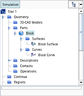
- Part Curves Option Dialog
-
Mark Sharp Edges
When activated, edges that occur between two faces that meet at an angle equal to or less than the specified Sharp Edge Angle are marked as part curves.
Sharp Edge Angle
The angle above which all edges are marked as part curves when marking sharp edges. If you set the angle to 50, then any angle above 50 is marked as a part curve and any angle below 50 is not.
Mark Free Edges
When activated, all free edges are marked as part curves.
Mark Non-manifold Edges
When activated, all non-manifold edges are marked as part curves.
Mark Patch Perimeters
Marks all edges that surround a patch (a collection of mesh faces on a part or region) as part curves.
Mark Part Surface Perimeters
Marks all edges that surround a part surface (a collection of patches on a geometry part) as part curves.
Mark Boundary Perimeters
Marks all edges that surround a boundary as part curves.
Automatically Fix Errors
Automatically fixes minor errors related to face quality, face proximity, and self-intersection.
Maintain Existing Edges
Keeps edges that are already defined as part curves.
- Composite Parts
- A composite part is a collection of geometry parts that are grouped together. In
Simcenter STAR-CCM+, composite parts have no assembly constraint details, meaning that you cannot constrain the parts with relation to the other parts in the composite part. When you import an assembly from an external CAD package, the position of the parts in space is honored and the geometry parts are brought in under a single composite part. This position of the imported geometry parts is not associative. If you manually move a geometry part, for example using the translate action, the geometry part moves without updating any of the other parts.

- Composite parts can contain complex assembly structures that include sub-assemblies, which themselves can contain further sub-assemblies, and so on. The final level is composed of one or more leaf parts.
