Preparing Geometry for Moving Reference Frame
The geometry of the model must be prepared in order to distinguish the moving portions of the geometry from the static portions.
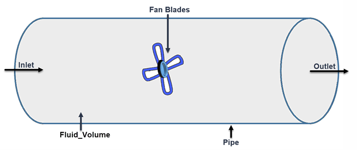
Before completing this procedure, make sure that you have a geometry part that represents the fluid volume. If necessary, extract the fluid volume from any surrounding solids.
The following image shows an example of a geometry suitable use with a rotational moving reference frame:
In order to split the initial fluid volume into a static and rotating part, you first create an additional volume shape that encloses the rotating part. With this additional shape, you can split out the part to which you later assign the rotating reference frame.
-
To create a cylinder shape part, for example:
- Right-click the node and select and place it around the rotating object.
-
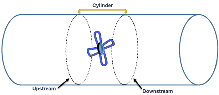
To ensure that the rotating region has separate upstream and downstream surfaces, you split the surfaces of the shape part:
- Right-click and select Split by angle.
-
Rename the surfaces of the cylinder to [upstream] and [downstream] depending on the direction of the flow. When you assign the parts to regions, these surfaces form interfaces between the static and rotating regions. See the following image:
Through a series of boolean operations, you can define and split a rotating part from the static part. Be sure to perform each operation in the sequence provided and execute them separately.
-
To split out a rotating region from the existing fluid volume, carry out the following steps:
-
Imprint Operation - generates necessary contacts between adjacent part surfaces.
- Right-click and select
- Select the Fluid_Rotate and Fluid_Static for the input parts and activate Perform CAD Boolean.
- Right-click and select Execute
The following image shows the rotating and static parts of the geometry.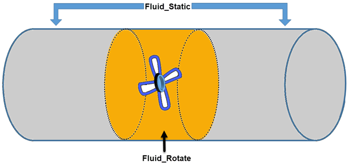
-
Imprint Operation - generates necessary contacts between adjacent part surfaces.
-
Assign parts to regions as follows:
Two new regions are created within the Region node. The Interfaces node also appears in the tree.
Continue to define and apply the reference frame.