Creating Sketch Chamfers
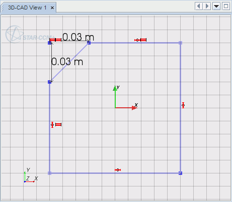
A sketch chamfer is a feature that makes a straight cut across the corner that is formed between two lines on a sketch.
You can only create chamfers between two lines at a time; these lines can be disjointed, intersecting or have a common end point. When the lines intersect each other, the chamfer is created between the two longest segments of the lines.
To create a sketch chamfer:
- Select the two sketch lines that you want to chamfer.
-
Right-click on one of these lines and select
.

The
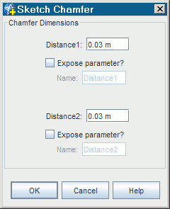
Sketch Chamfer dialog appears.


-
Enter values for
Distance 1
and Distance 2. These values define the size of the chamfer and are the distances that the chamfer will be from the point where the two lines meet.
Note You can define the chamfer using a numerical value, or by an expression using design parameters. Activate Expose Parameter ? for each distance property to expose it as a design parameter. - Click OK.
The chamfer is applied to the selected entities.


Two sets of coincidence constraints are added to the sketch when the chamfer is created. Two distance dimensions are also created; you can edit these dimensions to control the chamfer size.
| Note | The dimensions controlling the chamfer must be smaller than the length of the shortest original sketch line. Once created, the chamfer dimensions can be edited. The sketch chamfer feature can be undone/redone using the appropriate buttons in the Sketch in-place dialog. |