Splitting the Manikin Face Surface
The Fiala Thermal Comfort model requires a minimum of 58 part surfaces for the manikin geometry. The current geometry only contains 57 part surfaces. As the manikin has a single surface for the face, instead of the required left and right face surfaces, you split the surface into two distinct surfaces using the Intersect tool in the Surface Repair tool.
To split the manikin face surface:
- Right-click the node and select Repair Surface....
- In the Surface Repair Options dialog, click OK.
- Click anywhere in the CabinComfort - Repair Surface 1 window, then click F on your keyboard and zoom into the face of the manikin.
-
Intersect the manikin Face surface:
-
In the Repair Surface 1 window,
double-click on the face of the manikin.
-
In the Global tab, select
 (Intersect or Boolean selected
faces).
(Intersect or Boolean selected
faces).
-
For Face Set 1, click
 (Add selected faces to the
set).
(Add selected faces to the
set).
-
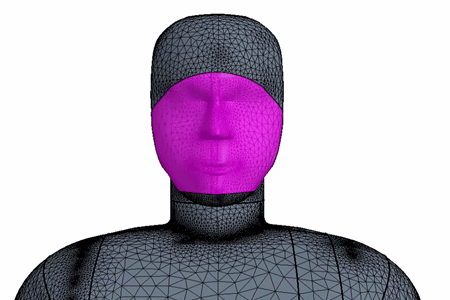
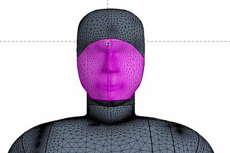
For Plane Origin, select
Pick..., then position the point as shown in
the image below:
-
In the Repair Surface 1 window,
double-click on the face of the manikin.
-
In the Repair tab, select
 (Flag edges as
feature).
(Flag edges as
feature).
When you split the manikin into the 58 part surfaces, you must
ensure that each part surface area matches the areas that are defined for the Fiala
manikin [958]. For the Face_L
and Face_R part surfaces the surface areas must equal 0.16
m2 and 0.14 m2 respectively. If you do not define the
surface areas correctly, Simcenter STAR-CCM+ can
produce incorrect results.
-
Calculate the areas of the face surfaces:
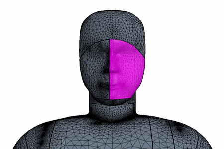
-
Select the part surface highlighted in the following image:
-
In the Query tab, select
 Area of selected face(s).
The Output window displays a target face area for the left hand face of around 0.16 m2.
Area of selected face(s).
The Output window displays a target face area for the left hand face of around 0.16 m2. -
Select the part surface highlighted in the following image:
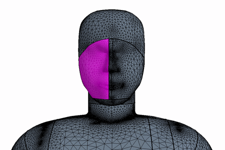
-
In the Query tab, select
Area of selected face(s).
The Output window displays a target face area for the right hand face of around 0.14 m2.
-
Select the part surface highlighted in the following image:
-
Define the face part surface names:
-
Select the part surface highlighted in the following image:
-
Select the part surface highlighted in the following image:
You now have the two required surfaces for the face. As you no
longer need the original face surface, you delete it.
- Right-click the node and select Delete
- Save the simulation.