Creating the Thermal Network Region for the Manikin
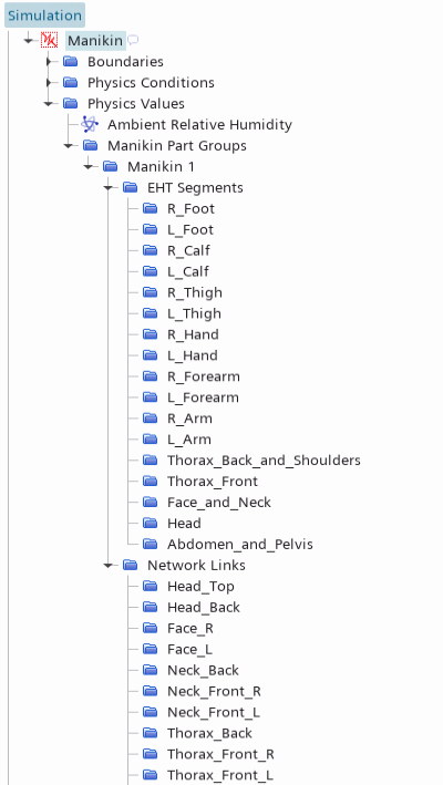
For thermal comfort simulations, you represent the manikin using a network region. A network region does not require meshing.
The surfaces of the Driver part are named according to the naming convention (see Manikin Segmentation Naming Convention Reference). Therefore, when you assign the manikin part to the network region, Simcenter STAR-CCM+ automatically assigns the part surfaces to the corresponding segments and links.
To create the thermal network region for the manikin:
- Right-click the Regions node and select .
- Rename the node to Manikin.
- Select the Manikin node and set Parts to .
- Select the node and set Value to 34.0 C.
-
Select the node and set Parts to .
Simcenter STAR-CCM+ automatically assigns the part surfaces to the corresponding segments and links.
Each segment or link must have an associated part surface.
However, there is no restriction on the number of part surfaces assigned to a link
or segment.
-
Expand the and Network Links nodes and make sure each
segment and link has an associated Part Surface.

-
Select the node and click
 (Custom Editor) next to the Part
Surfaces property.
- In the Driver - Part Surfaces dialog, activate and Face_R, then click OK.
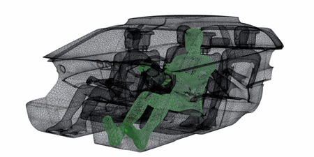
A polyhedral mesh with prism layers is set up for the
Cabin region. The mesh has a base size of 40 mm and a
prism layer total thickness of 8 mm. To create a closed surface of the car cabin and
accurately capture the geometric details, a surface wrapper operation is available
which wraps the geometry using a global base size of 10 mm and a custom control for
the manikin geometry. The manikin network region does not require a
mesh.
- Right-click the node and select Execute All.
-
Visualize the mesh:

- Save the simulation
