Fully Developed Flow and Energy
Fully developed flows occur in long tubes or tube banks. For simple flows without heat transfer or transported scalars, all flow variables except pressure can be treated as periodic. Pressure is typically modeled with a jump condition at the interface that compensates for the streamwise pressure drop through the system. When energy is present, a fully developed situation can be deemed to occur if the profiles of temperature and/or enthalpy become self-similar when using an appropriate scaling. In these cases, the self-similarity relations can be used to rescale the temperature profile from the interface boundary at the outflow to use at the inflow interface boundary.
so that the wall temperature and the bulk temperature must be specified.
For the constant heat flux assumption, the scaling law is:
so that bulk temperature must be specified.
Validity of the Fully Developed Energy Assumption
Consider the flow in a duct in which the streamwise coordinate is , and the cross-stream coordinate is . By definition, fully developed heat transfer exists when the heat transfer coefficient is independent of :
For a constant-property fluid, the bulk temperature is defined as:
and the mean velocity is defined as:
It is assumed that and are independent of , but is a function of . Since and are independent of , the following is obtained:
implying the existence of a dimensionless temperature profile:
or equivalently, since :
In the constant wall heat flux case, since both and are constant, equals a constant, so that:
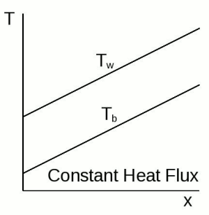
In other words, for a constant wall heat flux, both the bulk temperature and the wall temperature increase linearly with streamwise distance (see the figure of constant heat flux). This linear increase means that the temperature profiles at various streamwise locations differ only by a constant offset as follows:
This means that the problem can be solved without knowledge of the wall temperature, if one knows the increase in bulk temperature that is due to the (constant) wall heat flux.
The following image shows the behavior of bulk and wall temperatures for fully developed thermal fields with a constant heat flux:
In the constant wall temperature case, the partial derivative of temperature in the streamwise direction in the energy equation, which results from the convective term, is replaced with:
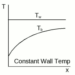
such that the rest of the energy equation can be written as a function purely of . However, the temperature profiles must be scaled using both the bulk temperature and the wall temperature. Furthermore, the bulk temperature increases non-linearly with streamwise distance in the duct, as shown in the following figure, resulting in a corresponding non-linear increase in local temperature.
The following image shows the behavior of bulk and wall temperatures for fully developed thermal fields with a wall temperature:
Therefore this section defines two and only two situations that permit fully developed heat transfer in a duct:
- Wall with constant heat flux
- Walls with a constant temperature
The resulting temperature profiles can be different, depending on the geometry. The following image shows the profiles for laminar constant-property flow through circular ducts.
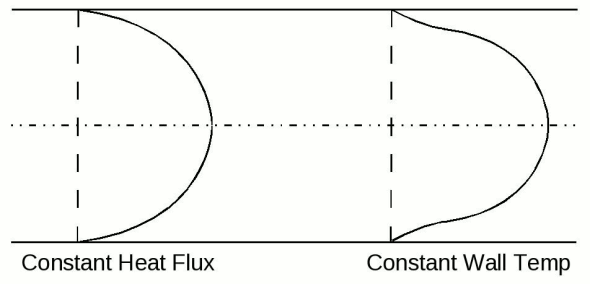
The constant heat flux boundary condition applies to a wall subject to electrical resistance heating or to a radiant flux. The constant temperature wall is approached when the outer wall is subject to phase change such as condensation or boiling. The two heating situations are also applicable to heat exchangers. The constant heat flux situation can correspond to a counterflow heat exchanger when the fluid capacity rates are the same. The constant temperature solution is applicable to any heat exchanger where one material has a very much larger capacity rate than the other. In addition to evaporators and condensers, the other material can be a heated solid of large thermal capacity.