Deforming a Freeform Surface Using Points
Typically, you create and move points to control the deformation of a freeform surface.
-
In the
3D-CAD View scene, right-click on the surface that you want to modify and select
.
To select multiple patches, use the <CTRL> key.
-
The
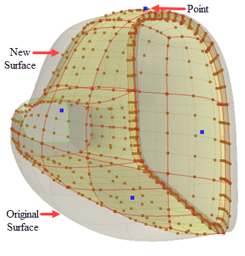
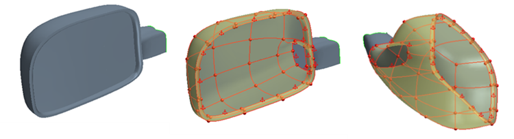
Freeform Surface panel appears and the surfaces that you selected are converted to a freeform surface. Freeform surfaces are accurate copies of the original surfaces. All the edges (boundary and interior) are displayed in red and all vertices (boundary and interior) are shown as red spheres. By default, the boundaries are constrained as fixed in order to maintain the original shape of the surface.
-
In the
Freeform Surface panel:
-
If required, adjust the resolution of the UV grid. In the
Display Options group box, click
 (Set Number of Grid Rows and Columns). Then, in the
Number of Grid Rows and Columns dialog, set the
Number of Grid Rows
and
Number of Grid Columns
that are suitable for your geometry, and click
OK. Grid density can control each surface separately.
The grid updates with the new settings. Increasing the resolution of the grid provides more areas, in a uniform distribution, in which control points can be placed. You can add further local U and V lines to provide local refinement to the grid.
(Set Number of Grid Rows and Columns). Then, in the
Number of Grid Rows and Columns dialog, set the
Number of Grid Rows
and
Number of Grid Columns
that are suitable for your geometry, and click
OK. Grid density can control each surface separately.
The grid updates with the new settings. Increasing the resolution of the grid provides more areas, in a uniform distribution, in which control points can be placed. You can add further local U and V lines to provide local refinement to the grid. -
If required, to create additional U and V curves, click
 (Create U Curve) and
 (Create V Curve) respectively.
You can only deform the freeform surface using points. You can place points anywhere on the freeform surface; however, you cannot enter the exact position using numerical values when placing the points. If you want increased accuracy and control for the point placement, place the points at intersections on the UV grid (see next step). You can increase the resolution of the UV grid, or you can add individual U and V curves only where they are needed.
(Create V Curve) respectively.
You can only deform the freeform surface using points. You can place points anywhere on the freeform surface; however, you cannot enter the exact position using numerical values when placing the points. If you want increased accuracy and control for the point placement, place the points at intersections on the UV grid (see next step). You can increase the resolution of the UV grid, or you can add individual U and V curves only where they are needed. -
Click
 (Create Point) and place the points on the freeform surface.
For added control, place points on a U curve, V curve, or at a grid intersection. When the mouse pointer approaches a grid intersection, the point snaps to the intersection. Points can be snapped to edges or vertices of the input faces. You can turn off this behavior by deactivating the
(Create Point) and place the points on the freeform surface.
For added control, place points on a U curve, V curve, or at a grid intersection. When the mouse pointer approaches a grid intersection, the point snaps to the intersection. Points can be snapped to edges or vertices of the input faces. You can turn off this behavior by deactivating the (Snap to Grid) display option.
You can add multiple control points, one after the other, by pressing the <CTRL> key.
(Snap to Grid) display option.
You can add multiple control points, one after the other, by pressing the <CTRL> key. -
To deform the freeform surface, click the point and move it using the triad that appears.
The triad offers you full control of the point movement. Each arrow direction restricts the movement to the X, Y, or Z axis. The triad that is used in the freeform tool behaves in the same way as the triad when sketching in 3D, see Creating a Sketch in 3D. As you start dragging the point, the freeform surface starts to deform. Any points that you place on the surface act as constraints if they are not moved. Placing points on the original freeform surface is a good way to restrict the influence of the deformation.
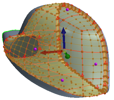
With a point selected, in the Displacement of Points group box, under the Coordinate System option, you can choose how the triad axes are aligned. You can have these axes aligned to the global coordinate system axes, or you can have the axes be normal to the selected surface. See Freeform Surface Panel Reference: Displacement of Points. By default, the coordinate system is set to Local when a new point is created.For greater control and accuracy of the point movement, you can enter the magnitude of the displacement in each direction under the appropriate field in the Displacement group box and click Apply.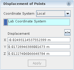
-
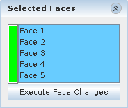
To add or remove faces, click on the
Selected Faces tab in the
Freeform Surface panel.
-
If required, adjust the resolution of the UV grid. In the
Display Options group box, click
- Click OK.