Freeform Surface Panel Reference
Modify the settings in the Freeform Surface panel to control the deformation of the freeform surface.
Face Selections
Allows you to add or remove faces to your freeform surface modeling operation.
Creation Options
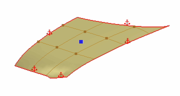
You control the deformation of the freeform surface using control points. Control points can only be placed on UV gridlines. You can create control points and U and V lines in the create options.
 (Create Point) (Create Point)
|
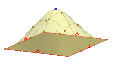
A point is a single vertex on the freeform surface. Points control the deformation of the freeform surface. You can place points anywhere on the freeform surface. For more precise control, you can place points on U and V gridlines or on gridline intersections. You can also create points by snapping to edges or vertices of the input faces.
 |
 (Create U Curve) (Create U Curve)
|
The freeform surface is made up of a UV grid, similar to a mesh, where you can add points to deform the freeform shape. A U or V curve is a line that can help define the shape of the freeform surface in the U and V directions respectively, when you snap points to them. |
 (Create V Curve) (Create V Curve)
|
|
 (Create Line on Surface) (Create Line on Surface)
|
A Line on Surface is a straight edge that you can draw on the freeform surface and is constructed from a start point and an end point. Moving a point on a line extends the influence of the deformation towards the other points on the same line.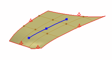 |
 (Create Spline on Surface) (Create Spline on Surface)
|
A Spline on Surface is a smooth curve that you can draw on the freeform surface and is composed from a series of points. Moving a point on a spline extends the influence of the deformation towards the other points on the same spline.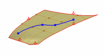 |
Displacement of Points
The displacement options control the magnitude and direction of deformation for each point on the freeform surface.
| Coordinate System | Specifies the coordinate system to use for each point. The Local coordinate system aligns the axis directions with those of the global coordinate system. The Normal coordinate system aligns the axis directions to the surface normals. You can also choose to use custom coordinate systems. |
| Displacement | Specifies the magnitude and direction of the displacement at the selected point. |
Boundary Constraint Options
Boundary constraints control the behavior of boundary edges on the freeform surface (that is, edges that bound the freeform surface). Edges on solid bodies and sheet bodies, as well as free edges on sheet bodies are all considered boundary edges.
 (Fixed) (Fixed)
|
Fixes the boundary so that it cannot move. This option is used to maintain the shape of the boundary edge.
 |
 (Tangent with Current Face) (Tangent with Current Face)
|
Maintains the tangency with the initial surface at the specified boundary edges. This option is useful if you want to maintain tangency with the specified edge of the current face. |
 (Tangent with Adjacent Faces) (Tangent with Adjacent Faces)
|
Creates a tangency between the freeform surface and adjacent faces. This option is useful for making the freeform surface blend into the surrounding surfaces, eliminating any sharp changes between surfaces. This option is only available when the freeform surface has neighbouring faces on the same surface. |
 (Movable) (Movable)
|
Allows boundary edges to move freely in any direction. This option is only available for free edges.
 |
 (Planar) (Planar)
|
Used to constraint the boundary edges to a plane. This option is only available for free edges.
 Choose one of the following
Planar Conditions:
A plane is automatically created and placed on the boundary edges by default. To choose a different plane, set Plane to Selected and pick a reference plane from the 3D-CAD feature tree. The boundary edges must be linear and lie on the plane. |
 (Sliding) (Sliding)
|
Used to extend surfaces while maintaining the overall shape of the surface. This option is primarily used with planar surfaces and is only available for free edges. One of the boundary edges must be movable for the surface to be able to slide in that direction. |
 (Rigid) |
Used to keep the
original shape of an edge while allowing it to move to satisfy the
other displacements and constraints. Only one design point is
recommended on the edge.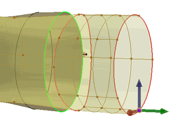 Any fixed edge in a loop may force all the connected rigid edges to stay fixed. |
 (Stiff) (Stiff) |
Used to keep the original shape of an
edge while allowing slight deviation along the arc length. The stiff
edge constraint allows smooth continuation of connected curves at
the end points. This option gives you more flexibility in deforming
faces where the edge does not maintain strict rigidity after
freeform surface deformation. 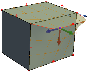 |
Display Options
 (Display Grid) (Display Grid)
|
Controls the display of the UV grid on the freeform surface. By default, the UV grid is turned on. |
 (Snap to Grid) (Snap to Grid)
|
Controls whether the mouse pointer snaps to intersections in the grid lines. This option is activated by default. When the grid display is turned off, the mouse pointer still snaps to the grid. |
 (Set Number of Grid Rows or Columns) (Set Number of Grid Rows or Columns)
|
Controls the number of U and V curves that appear on the freeform surface. In the Number of Grid Rows and Columns dialog, enter a value for Number of Grid Rows and Number of Grid Columns to increase/decrease the number of U curves and V curves respectively. |
 (Display Constraint Planes) (Display Constraint Planes)
|
Allows you to display planes to which entities are constraint to. |
 (Display Interior Edge Constraints) |
Allows you to display interior edges of the selected surface to define edge constraints. |