Controlling Freeform Surfaces Using Design Parameters
You can control the displacement of a control point on the freeform surface using design parameters in 3D-CAD.
To create a vector parameter:
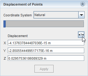
- With the Freeform Surface panel open, create a point and place it on the freeform surface, or click on an existing point, to display the displacement values.
-
In the
Displacement of Points group box, click
 (Expose Parameter).

-
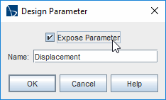
In the
Design Parameter dialog:
A vector design parameter is added to the Design Parameters node in the 3D-CAD feature tree. Points that are driven by design parameters appear in red in the 3D-CAD View scene, and cannot be modified interactively. When you click on these points, the triad does not appear.
Creating and Using Scalar Design Parameters to Drive Freeform Surfaces
You can use a scalar parameter to drive the displacement of a control point on a freeform surface.
There may be times where you are interested in controlling the displacement in a specific direction. You can create a scalar parameter and use this in the desired direction to control the magnitude of the displacement in that direction.
To create a scalar parameter to drive the displacement of a control point:
-
In the 3D-CAD feature tree, right-click the
Design Parameters node and select
.
It is recommended that you create scalar parameters before creating or editing a freeform surface, however, if you have the Freeform Surface panel open, you can click the 3D-CAD tab to switch to the 3D-CAD feature tree.A scalar design parameter is added to the Design Parameters node
- Right-click the new design parameter and rename it to something more appropriate, for example Height.
- Select the scalar design parameter and set the desired Value.
- Create or edit a freeform surface to display the Freeform Surface panel. .
- In the 3D-CAD View scene, select the control point that you want to be controlled by the scalar design parameter.
-
In the
Freeform Surface panel, in the
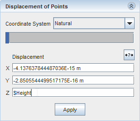
Displacement of Points group box, Click inside a displacement direction fields and type the name of the scalar parameter.
When referencing design parameters, you must use the $ symbol, for example $Height for the design parameter named Height.In this example, you control the displacement in the Z direction with the scalar parameter.

-
Click
Apply.
The point moves according to the value in the scalar parameter. Points that are driven by design parameters appear in red in the 3D-CAD View scene and cannot be modified interactively. When you click on these points, the triad does not appear.
