Multi-Part Solid Model Reference
The Multi-Part Solid model can simulate several parts of different compositions in a single region.
| Provided By | ||
| Example Node Path | ||
| Requires | Space: any Time: Steady or Implicit Unsteady Material: Multi-Component Solid |
|
| Activates | Model Controls (child nodes) | Solids. (See Defining Solid Components.) |
| Region Inputs | (See Assigning Parts to Materials.) | |
| Field Functions | Cell Part Index, Solid Material ID. (See Multi-Part Solid Field Functions Reference.) | |
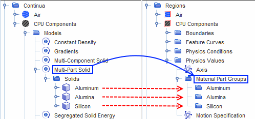
When a physics continuum containing the Multi-Part Solid model is applied to a region, a Material Part Groups node is added to the Physics Values manager for that region. You use the Material Parts Group node to map between solid materials and geometry parts.
The following diagram shows the Multi-Part Solid node in the physics continuum, and the Material Part Groups node in a region to which the physics continuum is applied:
Requirements
- Multi-part solids can only be used in simulations where geometry parts define the geometry. The identity of these geometry parts must be retained at the region level. Therefore, when you assign geometry parts to regions, include multiple geometry parts in the same region.
Select the One region for all parts option in the Region Mode menu of the Assign Parts to Regions dialog.
- When you have interfaces between parts, the best accuracy can be obtained by setting the interface type to Contact. In this instance, the thermal flux across the interface is calculated in a manner that accounts for the presence of discontinuous properties. Furthermore, Contact interfaces support the application of a Thermal Contact Resistance and/or Heat Source within the interface if necessary. In contrast, if you set the interface between parts to type Internal, the heat flux at the interface is calculated based on averaged properties. This calculation results in a certain amount of smoothing of the temperature field across the interface, which is not always realistic. Therefore, set interfaces between parts of dissimilar solid materials to Contact.
- If any material in the simulation has anisotropic thermal conductivity, create a dedicated physics continuum for that material. The Multi-Part Solid model does not currently support materials that require the Anisotropic method for Thermal Conductivity.
Workflow
To set up a simulation in Simcenter STAR-CCM+ with multi-part solids:
- Select the Multi-Part Solid model.
- Select Coupled Solid Energy or Segregated Solid Energy from the Optional Models group.
- Select a model from the Equation of State group.
- Assign each region to the proper continuum. Only a solid region is compatible with a continuum that contains the Multi-Part Solid model.
- Assign parts to materials.
- Change the interface type between solid parts that are in contact.
This model activates field functions that are useful for post-processing.
Multi-Part Solid Field Functions Reference
The following primitive field functions are made available to the simulation when the Multi-Part Solid model is used.
 Cell Part Index
|
The Index value of the part that is associated with a given cell. Generated by the meshing process. Also used in parts-based reporting. |
|
Solid Material ID
|
The ID value of the solid material that is associated with a given cell. Identifies which solid component in the continuum defines the material properties for that cell. Also allows visual association of cells defining parts with a particular material. |