Preparing Wall Heat Transfer Data in es-ice
Calculating spatially varying, cycle-averaged wall heat transfer data in es-ice produces CAE data, which can be imported into Simcenter STAR-CCM+. This es-ice post-processing facility generates a .dbs file, containing the CAE model and calculates eight data-sets.
As the .usr file can only contain six data-sets at most, es-ice writes two .usr files, with the data described below:
- Data file 1:
Register 1: Average Heat Transfer Coefficient (Watts/m2-K) Register 2: Average Near-Wall Gas Temperature (K) Register 3: Average Heat Flux (Watts/m2) Register 4: Average Wall Boundary Temperature (K) Register 5: Average y+ Register 6: Average Distance from Boundary to y+=100 (m) - Data file 2:
Register 1: Average Heat Transfer Coefficient at y+=100 (Watts/m2-K)
Register 2: Average Near-Wall Gas Temperature at y+=100 (K)
The nomenclature for the above equations is provided below:
| Notation | Description |
|---|---|
| Crank Angle (degrees) | |
| Start Crank Angle (degrees) | |
| End Crank Angle (degrees) | |
| Heat Transfer (W/m2-K) | |
| Heat Transfer at y+=100 (W/m2-K) | |
| Temperature of near-wall gas (K) | |
| Temperature of wall boundary (K) | |
| Temperature at y+=100 (K) | |
| Heat Flux (W/m2) | |
| Non-dimensional wall co-ordinate (see Eqn. (1584)) | |
| Distance from boundary to y+=100 (m) |
The solution data is defined with respect to cell IDs, which must match exactly to the cell IDs in the .dbs file. To ensure the cell IDs correlate, follow the procedure below to generate this solution data.
- Run an
es-ice analysis with the
Heat Transfer option selected in the
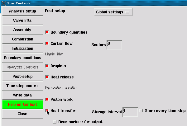
Star Controls > Post-processing > Global Settings panel. This generates heat transfer data (es-ice_htx.pos) while STAR is obtaining a solution.

- When the solver is complete, open the
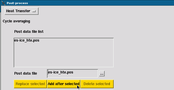
Post-process panel and select
Heat Transfer from the drop-down menu at the top of the panel.

- Click the ellipsis to select
es-ice_htx.pos from the file browser and then click
Add after selected. STAR has generated this file when running the analysis.

- Click
Load post data and enter an appropriate
Crank angle range to cover the last full engine cycle. Then click
Cycle average to calculate the cycle-averaged wall heat transfer data. The start crank angle ( in the equations above) is entered in the first text field, and the end crank angle () in the second text field.

- Specify the file names of the
.dbs and two
.usr files, set the database ID to 1 and click
Write cycle avg. The CAE model (.dbs) and the solution data (.usr) is located in the current working directory.

Currently, Simcenter STAR-CCM+ can only import coded (ASCII) format .usr files, whereas es-ice generates binary format files. Therefore, an extra step is required to convert the binary format file to a coded format file in pro-STAR.
- Import the
.dbs file into
pro-STAR using the following commands:
dbase, open, <filename>.dbs
dbase, get, 1
This ensures the cell IDs in the solution data match the CAE model.
- Read the binary format
.usr file into
pro-STAR using the following commands:
getu, <filename>.usr, cell, all, binary - Save the solution data to a coded format
.usr file with the following commands:
savu, <filename>.usr, all, coded, all - Repeat steps 2 and 3 for the second .usr file.