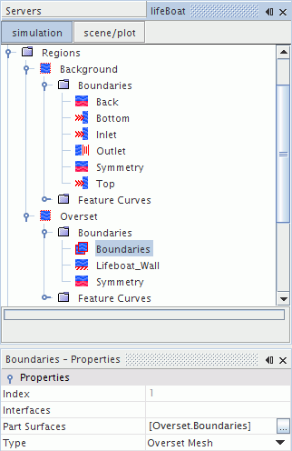
Creating Regions and Setting Boundary Types
Create regions from the Background and Overset parts.
- Multi-select the and Overset nodes.
- Right-click either selected node and select Assign Parts to Regions....
-
In the
Assign Parts to Regions dialog:
- Set Region Mode to Create a Region for Each Part.
- Set Boundary Mode to Create a Boundary for Each Part Surface.
- Select Do Not Create Interfaces From Contacts.
- Click Apply, and then Close.
To be able to create an overset interface between the two regions, assign the
Overset Mesh type to at least one boundary in the
Overset region. This boundary type applies to all the boundary surfaces of the
Overset region which are embedded inside the
Background region, and do not form part of the boat hull. Boundaries of the
Overset region which are coplanar with boundaries of the
Background region (in this case,
Symmetry plane) must be assigned the same boundary type.
Assign the boundary of each region to the correct type:
-
Edit the
node and set the boundary type for each surface as follows:
Node Boundary Type Back Symmetry Plane Bottom Velocity Inlet Inlet Velocity Inlet Outlet Pressure Outlet Symmetry Symmetry Plane Top Velocity Inlet -
Edit the
node and set the boundary type for each surface as follows:
Node Boundary Type Boundaries Overset Mesh Lifeboat_Wall Wall Symmetry Symmetry Plane The simulation tree appears as follows:
-
Save the simulation
 .
.