Generating the Neutral Surface using Blade Sketches
The Turbo Slicing Surface tool allows you to use blade sketches for generating a neutral surface. Using blade sketches is only available for axial geometries.
Before using the Turbo Slicing Surface tool, make sure that your geometry has a suitable fluid domain. See Extracting the Overall Fluid Volume.
-
In the Features toolbar, click the
 (Face Feature) option and
select
(Face Feature) option and
select  (Create Turbo Slicing
Surface).
The Turbo Slicing Surface panel appears.
(Create Turbo Slicing
Surface).
The Turbo Slicing Surface panel appears. - In the Turbo Slicing Surface panel, set Input Type to Blade Sketches.
When creating a neutral surface, the turbo slicing surface tool
checks that every blade sketch is a closed loop composed of two curves and two
vertices. The tool does nothing if any of the blade sketches do not satisfy these
conditions. Also, each blade profile must intersect with the leading and trailing
profiles at the blade profile vertices.
-
In the 3D-CAD View scene, select the sketches
that make up the profiles of a single blade in the right order (similar to the
requirement for the loft feature).
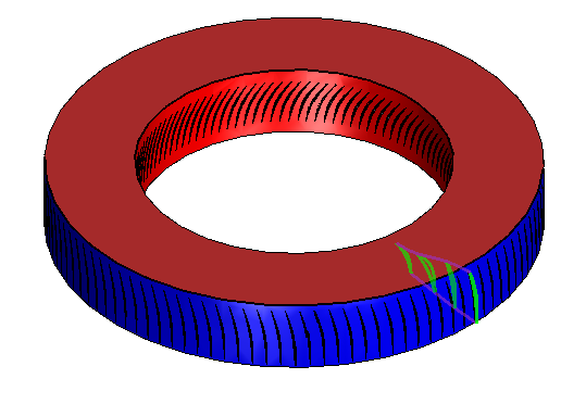
The tool does nothing if the sketches are not selected in sequence.The image below shows an example where the blade sketches highlighted in green are selected.

-
Click inside the Leading/Trailing Sketches group box to
activate it and, in the 3D-CAD View scene,
select the sketches of the leading edge and trailing edge.
The image below shows an example where the leading edge and trailing edge highlighted in purple are selected.

-
Click inside the Hub Faces group box to activate it
and, in the 3D-CAD View scene, select the faces
that make up the hub.
You are advised to only select the hub faces that envelop the selected blade, and that define the hub surface of revolution. It is not necessary to select all the faces that make up the hub. Do not select faces that are coincident with upstream or downstream boundaries.The image below shows an example where the hub face highlighted in red is selected.

-
Click inside the Shroud Faces group box to activate it
and, in the 3D-CAD View scene, select the faces
that make up the shroud.
In cases without a shroud, for example open propellers, the shroud faces are the outer boundary of the extracted fluid domain.The image below shows an example where the shroud face highlighted in blue is selected.

-
Click inside the Inlet Faces group box to activate it
and, in the 3D-CAD View scene, select the
faces that correspond to the inlets.
The image below shows an example where the inlet face highlighted in brown is selected.
-
Click inside the Outlet Faces group box to activate
it and, in the 3D-CAD View scene, select the
faces that correspond to the outlets.
The image below shows an example where the outlet face highlighted in light blue is selected. If a neutral surface can be calculated, a preview appears as shown below.

-
For geometries containing either non-planar inlets or outlets, or two or more
small inlets or outlets, activate the Auto Extend
Inlet/Outlet option.
For more information, see Turbo Slicing Surface Panel
-
Set the turbo slicing surface parameters so that the neutral surface fits
through the center of the blade. Also make sure that the areas where the neutral
surface meets the inlet and outlet are normal to these boundaries.
The surface must fully intersect all domain walls so that you can use it to slice the single blade passage from the overall fluid domain.See Turbo Slicing Surface Panel for a definition of the parameters.
- Click OK.