Repairing the Exhaust Tip
One of the exhaust tips is a sheet body with internal parts. Some of the surfaces are missing from this part which prevents 3D-CAD from using it as a solid body. In order to use this body in meshing, you must reconstruct the internal parts before converting it to a solid body.
-
First isolate the part for repair:
- Under the Body Groups node, multi-select the Exhaust Tip 1, Exhaust Tip 1 2, Exhaust Tip 1 3, and Exhaust Tip 1 4 nodes.
- Right-click one of the selected body nodes and select Show Only.
Before reconstructing the interior, you create a sketch plane
onto which you project one of the perforation holes. You can then use the projected
sketch to recreate the perforation holes once the interior of the exhaust tip is
fixed.
-
To create a sketch plane for the sketch of the perforation hole:
-
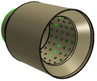
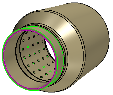
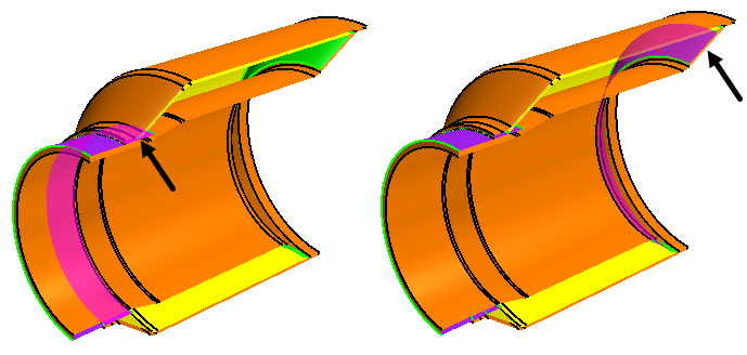
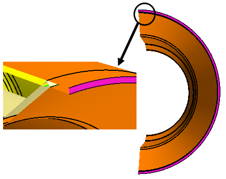
In the graphics window, rotate the part and select the edge that
connects the exhaust tip to the tail pipe as shown in the image below.
-
In the toolbar at the top of the 3D-CAD
View scene, click Display Cut Parts using
Multiple Planes.

-
In the Dynamic Sectioning panel,
within Section 1, first select
 (ZX Plane), which
activates a slice through the middle of the exhaust tip.
(ZX Plane), which
activates a slice through the middle of the exhaust tip.
-
In the Dynamic Sectioning dialog, now select
 (Reference Plane)
and then, in the graphics window, select Plane 3.
Confirm that you have selected the correct slicing plane by moving the
exhaust tip around in the graphics window.
(Reference Plane)
and then, in the graphics window, select Plane 3.
Confirm that you have selected the correct slicing plane by moving the
exhaust tip around in the graphics window.
-
In the Vis toolbar, click
 (Save-Restore-Select Views) and select .
-
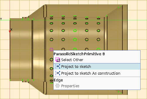
In the graphics window, zoom in closely and right-click the edge of the
hole as shown in the image below and select Project to
sketch.
-
In the graphics window, rotate the part and select the edge that
connects the exhaust tip to the tail pipe as shown in the image below.
The projected perforation hole is used in a later step for
recreating all of the channel holes. Before then, you use the Search Tool to find
the existing channel holes in order to delete them.
-
To create a design filter that finds all the channel faces:
-
To open the Search Tool panel, on the right side of the 3D-CAD View scene, click
 (Show Filter).
-
In the Design Filter 1: Input panel,
set Selection Mode to
 (Selected Entities).
-
For Object Type, select
 Bodies .
-
To the right of the Object Type Selection box, click the
 (Object Selector)
and select Exhaust Tip 1. Close the object
selector by clicking the same button as you did when opening it.
(Object Selector)
and select Exhaust Tip 1. Close the object
selector by clicking the same button as you did when opening it.
-
For Input Type, select
 Faces .
-
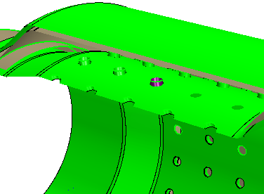
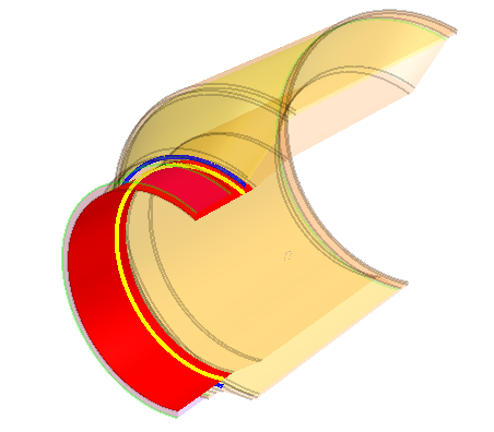
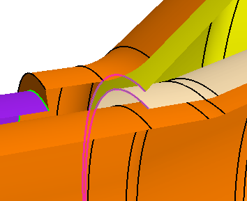
In the 3D-CAD View scene, rotate the
part and zoom in closely to select a channel face, as shown in the
example below.
-
Once you have selected the face, click Search to
locate all the similar faces in the body.
All the channel faces are identified and selected in the geometry. In total 84 faces are found by the Search Tool.

-
To open the Search Tool panel, on the right side of the 3D-CAD View scene, click
-
Use the results from the Search Tool as inputs to the Delete Faces operation:
- Under the Design Filters node, right click the Channel Faces node and select Delete.
- In the Delete Faces panel, click OK.
-
Use the Fill Holes operation to fill the perforation holes:
-
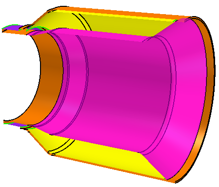
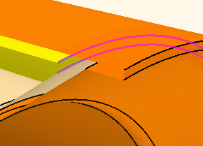
In the Fill Holes panel, click within the
Exclude Holes box and then, in the graphics
window, multi-select the two edges as shown below.

-
In the Fill Holes panel, click within the
Exclude Holes box and then, in the graphics
window, multi-select the two edges as shown below.
Due to missing faces, the inner cavity within the Resonator cannot be
formed correctly. To overcome this problem, you first move redundant surfaces and
then recreate the faces that surround the inner cavity.
-
Use the Imprint tool to split the faces where the Exhaust Tip
1 and Exhaust Tip 1 2 bodies intersect:
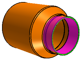
- Within the Body Groups node, multi-select the Exhaust Tip 1 and Exhaust Tip 1 2 nodes, right-click and select .
- In the Imprint Bodies panel, click OK.
-
Use the Delete Faces operation to remove unwanted faces inside the exhaust tip:
-
In the toolbar at the top of the 3D-CAD View
scene, change Color Mode to
 (Distinguish Bodies).
-
In the 3D-CAD View scene,
multi-select the faces as shown in the images below.
-
In the toolbar at the top of the 3D-CAD View
scene, change Color Mode to
-
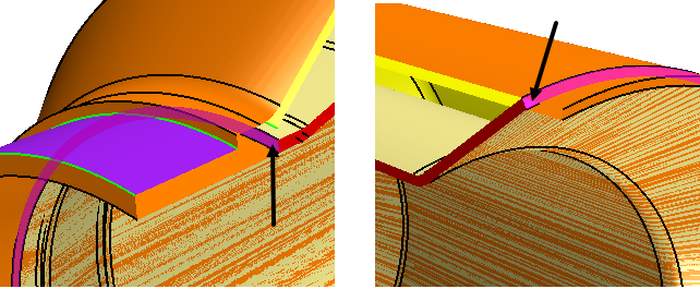
To help in selecting the right portion of the inner surface:
-
Multi-select the inner face at the entrance to the tip and the leading
edge of the floating inner surface as shown below.

-
In the Split Faces dialog, set Max
Project Distance to 5.0 mm.
-
Multi-select the inner face at the entrance to the tip and the leading
edge of the floating inner surface as shown below.
-
Select the inner surface and create a shell body as follows:
-
While pressing <CTRL>, click the first inner (selected) face at the
entrance to the tip; this action deselects this first face.
-
While pressing <CTRL>, click the first inner (selected) face at the
entrance to the tip; this action deselects this first face.
-
Only the upper surface of the thickened body is required. To delete the other
surfaces:
-
Multi-select the thin faces at each end of the thin body as shown
below.
-
Multi-select the thin faces at each end of the thin body as shown
below.
-
To provide a consistent set of edges for a bridging surface near the outlet of
the tip, create a plane and use it in a boolean slice:
-
Select the face as shown in the image below.
-
Select the face as shown in the image below.
-
Create bridging surfaces at the start and end of the inner volume that you are
forming:
-
Rotate the exhaust tip and multi-select the free edges above the
projected edge that was created from the Split Faces By Edge
Projection tool.
-
For the bridging surface near the end of the tip, multi-select the free
edges as shown in the image below.
-
In the toolbar at the top of the 3D-CAD View
scene, select the
 (Toggle Section
View) icon to deactivate the dynamic sectioning scene.
(Toggle Section
View) icon to deactivate the dynamic sectioning scene.
Exhaust Tip 1 4 is now a solid body that represents the inner volume of the exhaust tip. -
Rotate the exhaust tip and multi-select the free edges above the
projected edge that was created from the Split Faces By Edge
Projection tool.
- Under the Body Groups node, multi-select Exhaust Tip 1 and Exhaust Tip 1 2, right-click on the nodes and select Sew.
- In the Sew Sheet Bodies panel, click OK.
- Multi-select Exhaust Tip 1 and Exhaust Tip 1 4, right-click and select .
- In the Subtract Bodies panel, click OK.
-
Reconstruct the perforation holes:
-
Rotate the part and select the face inside the exhaust tip as shown
below.
-
Rotate the part and select the face inside the exhaust tip as shown
below.
- Multi-select all the feature nodes from Plane 2 to Circular Pattern Cut 1, right-click on the selected features and select Group.
- Rename the feature group to Repairing the Exhaust Tip.
- Save the simulation.