Repairing the Resonator and Transforming the Exhaust Tip
After you import the exhaust geometry, you use the tools in 3D-CAD to convert the Resonator part to a solid body. Then, you create two coordinate systems and use a transform operation to move the exhaust tip to its original position.
-
In the Vis toolbar, click
 (Save-Restore-Select Views)
and set to Parallel.
(Save-Restore-Select Views)
and set to Parallel.
-
In the toolbar at the top of the 3D-CAD View
scene, click
 (Model Visibility) and
activate the All Edges option. Also, change
(Model Visibility) and
activate the All Edges option. Also, change  (Color
Mode) to
(Color
Mode) to  (Gray Color).
The image below shows two parts displayed in brown indicating that they are sheet bodies.
(Gray Color).
The image below shows two parts displayed in brown indicating that they are sheet bodies.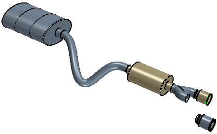
Before repairing these parts, it is good practice to check the
validity of the bodies. To run a validity check:
-
At the top of the 3D-CAD tree, right-click the Exhaust
node and select
 (Check
Validity).
A message with the results of the validity check is printed in the Output window:
(Check
Validity).
A message with the results of the validity check is printed in the Output window:All bodies of model are valid. -
To convert the Resonator part to a solid body:
- Under the Body Groups node, right-click the Resonator node and select Sew.
- In the Sew Sheet Bodies panel, click OK.
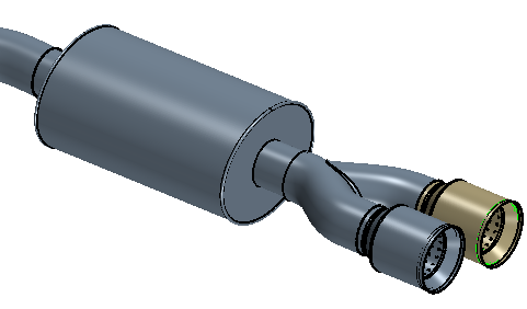
After executing the operation, the resonator part turns gray in the graphics window. The gray color indicates that the part is now a solid body.
In this tutorial one of the exhaust tips is misplaced. In
order to move the part back to its original position at the end of one branch of the
tail pipe, you must create two coordinate systems and then use a transform operation
to move it.
To move the exhaust tip to its original position:
-
First, create the coordinate system for the target location:
-
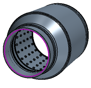
Find the center point on the open branch of the Tail Pipe. To do this,
in the graphics window, select the inner edge (circle) of the open
branch of the Tail Pipe, right-click and choose .

-
Find the center point on the open branch of the Tail Pipe. To do this,
in the graphics window, select the inner edge (circle) of the open
branch of the Tail Pipe, right-click and choose .
-
Create a coordinate system for the initial location of the exhaust tip:
-
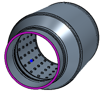
Select the inner edge of the exhaust tip as shown in the following
image.
-
Select the face on the inner end of the Exhaust Tip.
-
Select the inner edge of the exhaust tip as shown in the following
image.
-
To implement the change of position for the exhaust tip:
The exhaust tip must be moved within the tail pipe by a small amount, along
the Z-axis of the Target CSys.
-
To move the exhaust tip:
- Under the Body Groups node, right-click Exhaust Tip 2 and select .
- In the Translate Bodies panel, within Translation Definition, set Coordinate System Source to use the Target CSys for its Reference Coordinate System.
- Also within the panel, set Translation Vector to [0.0, 0.0, 0.005] m m m.
- Click OK.
-
Under the Features node, multi-select the
Point 1, Plane 1,
Target CSys, Point 2, and
Initial Exhaust Tip CSys nodes, right-click and
select Hide.
3D-CAD allows you to organise features in the simulation tree by grouping
them together. To group features:
- Within the Features node, multi-select the features from SewSheetBodies 1 to TransformBody 1, right-click and select Group.
- Rename the feature group to Resonator and Exhaust Tip Fixes.
- Save the simulation.