Extracting the Internal Volume
Before extracting the internal volume, use the Dynamic Sectioning tool to visually inspect the parts for gaps. Once you have identified the gaps in the geometry, use the extend solid tool to close them.
- Right-click a blank area in the 3D-CAD View scene and select Restore Hidden Bodies.
-
Use the Dynamic Sectioning tool to visually inspect the geometry:
-
In the toolbar at the top of the 3D-CAD
View scene, click Display Cut Parts using
Multiple Planes.

-
In the Vis toolbar, click
 (Save-Restore-Select Views) and select .
-
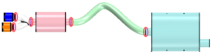
If you zoom closely towards the resonator part, you will notice gaps
between the body and its connecting parts.

-
Use the dynamic sectioning tool to visually inspect the remaining
parts. You will notice that there are gaps between each connecting
parts.
The image below shows where the gaps are present in the geometry.
-
In the toolbar at the top of the 3D-CAD
View scene, click Display Cut Parts using
Multiple Planes.
-
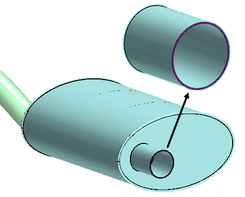
Use the Split Faces tool to project the edge of the tail pipe onto the
resonator:
-
Zoom in closely towards the gap and select the edge of the tail pipe
that lies above the face of the resonator, as shown in the image below.

-
Repeat the steps above to include the edges and faces as shown in the
image below.

-
Repeat the steps above to project the edge from the connecting pipe
onto the muffler. For this operation, in the Split
Faces panel, set Max Projection
Distance to 3.0 mm.


-
Zoom in closely towards the gap and select the edge of the tail pipe
that lies above the face of the resonator, as shown in the image below.
-
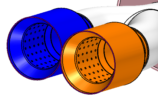
Use the Extend Solid tool to fill the gaps:
-
Select the face under the tail pipe, as shown in the image below.

-
Click OK.

-
Select the face under the tail pipe, as shown in the image below.
Once you have filled all the gaps, you use the extract
internal volume to create a fluid volume.
-
To carry out an internal volume extraction:
-
In the toolbar at the top of the 3D-CAD View
scene, select the
 (Toggle Section
View) icon to deactivate the dynamic sectioning scene.
(Toggle Section
View) icon to deactivate the dynamic sectioning scene.
-
At the bottom of the 3D-CAD View
scene, select the
 (Face Feature) menu
and select Extract Internal Volume.
(Face Feature) menu
and select Extract Internal Volume.
-
Click the
 (Object Selector)
icon on the right of the Enclosing Bodies box.
(Object Selector)
icon on the right of the Enclosing Bodies box.
-
In the Object Selection panel, select all the
bodies, then click the icon again when done.
-
Click within the Inlet/outlet Edges or Faces box
and select the following faces:
- The inlet face of the resonator
- The outlet faces of both exhaust tips
Once you have selected the faces, normally a preview of the solid body appears in the 3D-CAD View scene when an internal volume is found. For this case, the preview is not shown which indicates that there might be a leak in the geometry. To identify leaks:
- The inlet face of the resonator
-
Switch the Extraction Mode to
 (Detect Leaks
and Extract Liner).
(Detect Leaks
and Extract Liner).
-
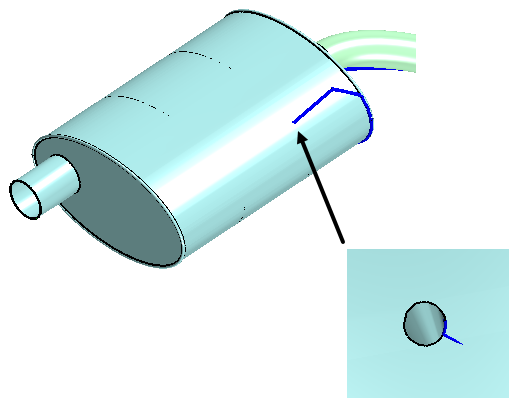
In the graphics window, zoom in closely towards the leak, then hold the
CTRL key and select the edge of the hole.
The image below shows the leak path to the muffler and if you zoom in closely you will find the leak hole.
 When no further leaks are detected, a yellow preview of the solid body is shown in the scene.
 -
Switch the Extraction Mode to
 (Extract
Internal Volume).
(Extract
Internal Volume).

-
In the toolbar at the top of the 3D-CAD View
scene, select the
- Multi-select all the new feature nodes, then right-click on the selected features and select Group.
- Rename the feature group to Extracting Internal Volume.
- Save the simulation.