Constitutive Relations
Maxwell's equations and the electric charge continuity equation do not form a closed set, as only three out of five equations are independent. Constitutive relations complete the set of equations by specifying the connection between the electric and magnetic fields.
Permittivity and Permeability
The constitutive relations between the electric field and the electric flux density , and between the magnetic field and the magnetic flux density can be generalized as:
where the permittivity describes the behavior of the material in response to an electric field, and the magnetic permeability describes the behavior of the material in response to a magnetic field. The inverse of the magnetic permeability is called the magnetic reluctivity, .
For materials other than ferroelectrics and ferromagnets, Eqn. (4219) and Eqn. (4220) are approximately linear.
In general, and are represented by second-order tensors, which define linear transformations between the vectors - and - , respectively.
For example, for a 3D domain, Eqn. (4219) can be written in matrix form as:
or, for a 2D domain on the x-y plane, as:
For homogeneous materials, the components of and do not depend on the position inside the material. For inhomogeneous materials, the components are functions of the position.
In the special case of isotropic materials, and reduce to diagonal matrices, with diagonal components and , and can therefore be defined using scalar quantities. Specifically, can be defined with respect to the vacuum permittivity, , as , where is called the relative permittivity. can be defined with respect to the vacuum permeability, , as , where is called the relative permeability. For paramagnetic materials, , whereas diamagnetic materials show .
Ferromagnetic materials show a nonlinear response to applied electromagnetic fields. For this type of materials, Eqn. (4220) becomes a nonlinear functional equation [848]:
In general, temperature changes can affect the magnetic permeability of ferromagnetic and paramagnetic materials. It is often convenient to express the dependence of on temperature through the magnetic susceptibility , which is defined as:
The dependence of on temperature can be approximated as:
where is the magnetic susceptibility at ambient temperature ( ) and is the susceptibility temperature factor, with .

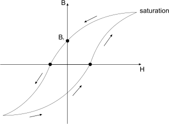
The image shows the magnetization process, where increases with until the material reaches saturation, and the demagnetization process, where decreases with until the material reaches (negative) saturation. Materials that exhibit a non-zero magnetic flux density, , when the applied magnetic field is zero, , are called permanent magnets. is called the remanent magnetic flux density.
For linear materials and soft materials which operate in the first quadrant of the characteristic, the energy density stored in the magnetic field is defined as:
For linear materials, the energy density is equal to the coenergy density, which is defined as:
Electrical Conductivity: Generalized Ohm's Law
The relationship between the electric current density and the electric field is described by the generalized Ohm's law:
where the electrical conductivity describes the behavior of the material in response to electric currents. Like and , is generally defined by a second-order tensor, and reduces to a scalar in isotropic conducting materials.
- Electrical Conductivity of Porous Materials
- In Simcenter STAR-CCM+, you can model porous materials in one of two ways—using porous regions (legacy method), or fluid regions with the Porous Media model (recommended method).