Electrodynamic Potential Models
In low-frequency electrodynamic applications, Simcenter STAR-CCM+ calculates the electric current density induced by the non-rotational component of the electric field, from the electric potential.
Electrodynamic Potential Equations
Simcenter STAR-CCM+ provides different methods for computing the electric potential. The first method is generally suitable for all electrodynamic applications, whereas the second method is specific to electric potentials with single harmonic time dependence (see Harmonic Time Dependence).
- Electrodynamic Potential
-
Simcenter STAR-CCM+ computes the electric potential from:
(4277)which is obtained by integrating Eqn. (4242) over the cell domain. Simcenter STAR-CCM+ discretizes and solves Eqn. (4277) using the finite volume method.
The second term on the left-hand side represents the eddy currents induced by a time-varying magnetic field. Simcenter STAR-CCM+ computes this term from Eqn. (4241). When Simcenter STAR-CCM+ does not solve for the magnetic vector potential, this term is not included in the equation.
- Harmonic Balance FV Electrodynamic Potential
- For potentials with single harmonic time dependence, Simcenter STAR-CCM+ computes the complex electric potential from:
Source Terms
The source terms on the right-hand side of Eqn. (4277) and Eqn. (4278) represent electric currents flowing through the bounding surface .
The right-hand side of Eqn. (4277) and Eqn. (4278) is typically zero. However, to account for unresolved physics, Simcenter STAR-CCM+ provides two user-defined sources, the transfer current density , which is a complex quantity in Eqn. (4278), and the electromotive force density , which is only available for Eqn. (4277).
In Eqn. (4242), these terms are implicitly included in the term, .
Additional sources of electric current density can contribute to Eqn. (4277), for example, the electric current density induced by an electrically conducting fluid in motion. These effects are discussed in specific sections.
Boundary and Interface Conditions
At the domain boundaries, the solution must satisfy either Dirichlet boundary conditions, which define the electric potential , or Neumann boundary conditions, which define the component of the electric potential gradient normal to the boundary. The following implementation applies to both the electric potential (Eqn. (4277)) and the complex electric potential (Eqn. (4278)). For the complex electric potential, the quantities prescribed at boundaries and interfaces are generally complex.
At a boundary face , the Dirichlet b.c. is implemented as:
where is the face area vector, is the vector between the cell face and the cell centroids, and is the electrical conductivity of the material. accounts for additional sources of electrical resistance. If then Eqn. (4279) reduces to a basic Dirichlet boundary condition that specifies the potential value at the boundary, .
The same condition can be prescribed at interfaces:
where the indices 0 and 1 identify boundary-0 and boundary-1 (that is, the two sides of the interface). The energy that is dissipated by the electric current at contact interfaces does not make any contribution to the energy equation, unless you explicitly model Joule heating or thermoelectricity phenomena. See Joule Heating and Thermoelectricity.
- electric current density (see Eqn. (4228))
- total electric current through , that is: (4282)
- specific electric current , that is, the component of normal to : (4283)
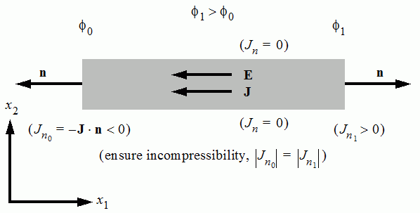
where is the boundary surface normal. A negative value of means that the electric current density goes in the direction of the boundary surface normal (that is, ).
- current-voltage characteristic, which defines the I-V curve representing the relationship between the electric current flowing through the boundary and the electric potential at the boundary. In electrochemistry applications, this relationship is often defined using the Butler-Volmer equation. For more information, see Butler-Volmer Current-Potential Characteristic.

where is the surface area and is a unit area integrated over the boundary or interface .